1 - 26
GEN
INFO
FEATURES
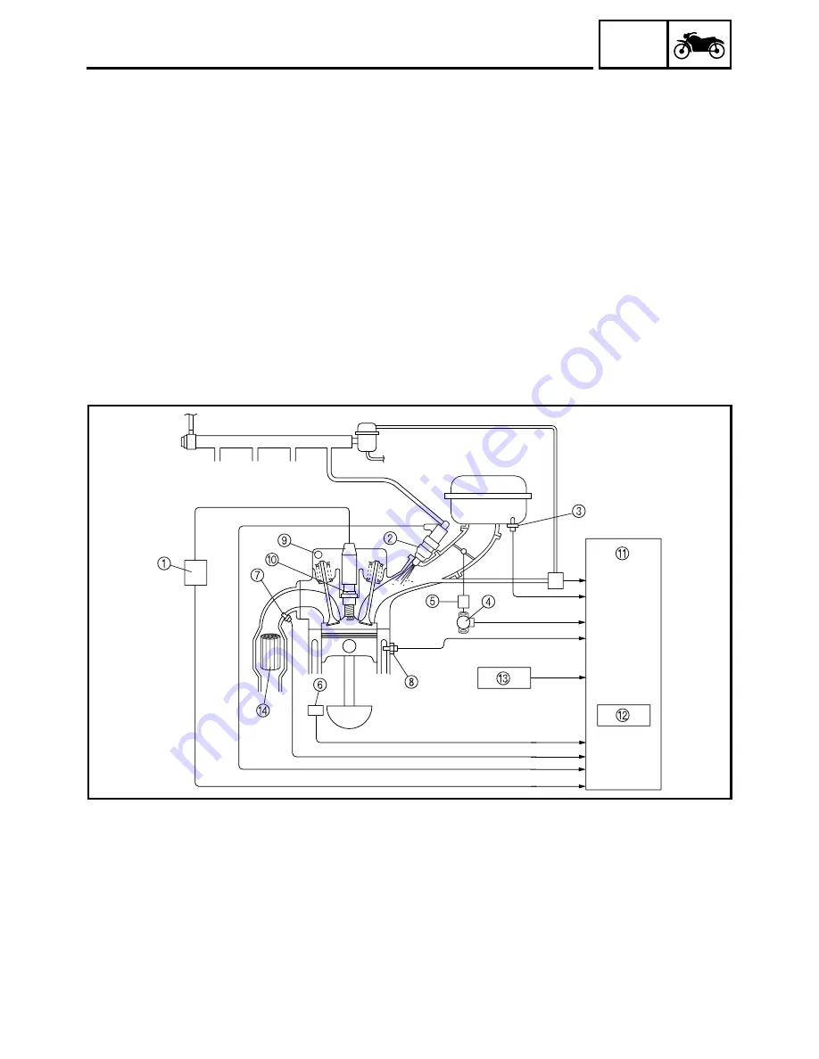
THREE-WAY CATALYTIC CONVERTER SYSTEM
System outline
This is a highly efficient exhaust gas cleaning system that effects air-fuel control through a joint
effort by the FI system, O
2
sensor, and the three-way catalytic converter system. By effecting com-
prehensive control of the air-fuel ratio in this manner, this system reduces the CO, HC, and NOx in
the exhaust gases.
The FI system controls the mixture to an optimal air-fuel ratio (basic air-fuel ratio) that matches the
operating condition of the engine in order to realize an ideal combustion.
Furthermore, an O
2
sensor that detects the concentration of oxygen that remains in the exhaust gas
is provided in the exhaust pipe for the purpose of maximizing the performance of the three-way cat-
alytic converter and to clean the exhaust gas at a high degree of efficiency. Based on this data, the
ECU applies more precise compensation to the basic air-fuel ratio, in order to maintain the mixture
in the vicinity of the stoichiometric air-fuel ratio of 14.7:1.
Through the joint effort of these control systems, the exhaust gas is cleaned in a highly efficient
manner without sacrificing engine performance.
Three-way catalytic converter system diagram
1
Ignition coil
2
Injector
3
Intake temperature
sensor
4
Throttle position sen-
sor
5
Intake air pressure
sensor
6
Crankshaft position
sensor
7
O
2
sensor
8
Coolant temperature
sensor
9
Cylinder identification
sensor
0
Spark plug
A
ECU
B
Igniter
C
Atmospheric pressure
sensor
D
Catalytic converter
Содержание FJR1300
Страница 1: ...LIT 11616 16 18 5JW 28197 10 FJR1300R FJR1300RC SERVICE MANUAL ...
Страница 6: ......
Страница 82: ...2 22 SPEC TIGHTENING TORQUES Cylinder head tightening sequence Crankcase tightening sequence ...
Страница 89: ...2 29 SPEC 1 Crankshaft 2 Main axle 3 Drive axle OIL FLOW DIAGRAMS ...
Страница 90: ...2 30 SPEC 1 Oil nozzle 2 Main gallery bolt 3 Crankshaft OIL FLOW DIAGRAMS ...
Страница 91: ...2 31 SPEC 1 Main axle 2 Drive axle 3 Oil delivery pipe OIL FLOW DIAGRAMS ...
Страница 92: ...2 32 SPEC 1 Exhaust camshaft 2 Oil check bolt 3 Intake camshaft OIL FLOW DIAGRAMS ...
Страница 93: ...2 33 SPEC 1 Oil check bolt 2 Crankshaft 3 Oil cooler 4 Oil pump 5 Oil strainer 6 Oil pipe OIL FLOW DIAGRAMS ...
Страница 94: ...2 34 SPEC 1 Crank pin 2 Crankshaft OIL FLOW DIAGRAMS ...
Страница 95: ...2 35 SPEC 1 Rear balancer 2 Oil delivery pipe 3 Crankshaft 4 Front balancer 5 Crank pin OIL FLOW DIAGRAMS ...
Страница 97: ...2 37 SPEC 1 Main axle 2 Drive axle 3 Middle drive shaft OIL FLOW DIAGRAMS ...
Страница 98: ...2 38 SPEC COOLING SYSTEM DIAGRAMS 1 Radiator COOLING SYSTEM DIAGRAMS ...
Страница 99: ...2 39 SPEC 1 Water jacket joint 2 Oil cooler COOLING SYSTEM DIAGRAMS ...
Страница 100: ...2 40 SPEC 1 Thermostat assembly 2 Coolant reservoir 3 Radiator 4 Oil cooler COOLING SYSTEM DIAGRAMS ...
Страница 101: ...2 41 SPEC 1 Coolant reservoir 2 Radiator 3 Water pump COOLING SYSTEM DIAGRAMS ...
Страница 107: ...2 47 SPEC CABLE ROUTING 1 Tail brake light lead ...
Страница 196: ...3 80 CHK ADJ ADJUSTING THE HEADLIGHT BEAMS ...
Страница 288: ...4 92 CHAS 3 Install bearing 1 to the swingarm Installed depth a 4 0 mm 0 16 in SWINGARM ...
Страница 531: ...8 35 ELEC LIGHTING SYSTEM ...
Страница 570: ......
Страница 571: ...YAMAHA MOTOR CO LTD 2500 SHINGAI IWATA SHIZUOKA JAPAN PRINTED IN U S A ...


