


7 - 4
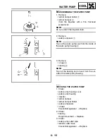
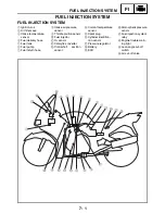
FI
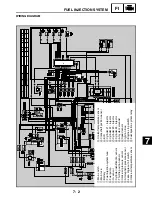
FUEL INJECTION SYSTEM
Engine trouble warning light indication and FI system operating conditions (normal mode)
Warning light
indication
ECU’s operating
condition
FI operating condition
Starting and driving
ON and OFF *1
Self-diagnostic func-
tion in operation
FI function in operation Able
Blinking *2
Warning control when
unable to start engine
Operation stopped
Unable
Continuous ON
Detecting malfunction
Gives driving instruc-
tions with substitute
characteristics in accor-
dance with the descrip-
tion of the malfunction.
Able/Unable depend-
ing on self-diagnostic
fault code
OFF *3
Possibly a blown warn-
ing light bulb or a mal-
function in power
supply system or ECU
*1
The warning light illuminates 1.4 seconds each
time the main switch is turned ON. The ECU
performs a self diagnosis during this time and
turns OFF the light thereafter.
*2
Warning control when unable to start engine
This control is effected when any one of the
conditions listed below is present and the
starter switch is turned ON:
a. Battery voltage below the specified value
(defective fuel injection system relay, engine
stop switch turned OFF, or drained battery)
b. One of the fault codes listed below has
been detected (self-diagnostic code 12, 19,
30, 33, 34, 41, or 50 is output):
(12: faulty crankshaft position sensor sig-
nal)
(19: open circuit in sidestand input line)
(30: motorcycle has fallen over)
(33, 34: faulty ignition)
(41: open or short circuit in lean angle cut-
off switch)
(50: ECU memory check error)
Main switch Main switch
Light ON for
1.4 seconds
Light
OFF
Light
OFF
Initialize
Engine trouble
warning light
Содержание FJR1300
Страница 1: ...LIT 11616 16 18 5JW 28197 10 FJR1300R FJR1300RC SERVICE MANUAL ...
Страница 6: ......
Страница 82: ...2 22 SPEC TIGHTENING TORQUES Cylinder head tightening sequence Crankcase tightening sequence ...
Страница 89: ...2 29 SPEC 1 Crankshaft 2 Main axle 3 Drive axle OIL FLOW DIAGRAMS ...
Страница 90: ...2 30 SPEC 1 Oil nozzle 2 Main gallery bolt 3 Crankshaft OIL FLOW DIAGRAMS ...
Страница 91: ...2 31 SPEC 1 Main axle 2 Drive axle 3 Oil delivery pipe OIL FLOW DIAGRAMS ...
Страница 92: ...2 32 SPEC 1 Exhaust camshaft 2 Oil check bolt 3 Intake camshaft OIL FLOW DIAGRAMS ...
Страница 93: ...2 33 SPEC 1 Oil check bolt 2 Crankshaft 3 Oil cooler 4 Oil pump 5 Oil strainer 6 Oil pipe OIL FLOW DIAGRAMS ...
Страница 94: ...2 34 SPEC 1 Crank pin 2 Crankshaft OIL FLOW DIAGRAMS ...
Страница 95: ...2 35 SPEC 1 Rear balancer 2 Oil delivery pipe 3 Crankshaft 4 Front balancer 5 Crank pin OIL FLOW DIAGRAMS ...
Страница 97: ...2 37 SPEC 1 Main axle 2 Drive axle 3 Middle drive shaft OIL FLOW DIAGRAMS ...
Страница 98: ...2 38 SPEC COOLING SYSTEM DIAGRAMS 1 Radiator COOLING SYSTEM DIAGRAMS ...
Страница 99: ...2 39 SPEC 1 Water jacket joint 2 Oil cooler COOLING SYSTEM DIAGRAMS ...
Страница 100: ...2 40 SPEC 1 Thermostat assembly 2 Coolant reservoir 3 Radiator 4 Oil cooler COOLING SYSTEM DIAGRAMS ...
Страница 101: ...2 41 SPEC 1 Coolant reservoir 2 Radiator 3 Water pump COOLING SYSTEM DIAGRAMS ...
Страница 107: ...2 47 SPEC CABLE ROUTING 1 Tail brake light lead ...
Страница 196: ...3 80 CHK ADJ ADJUSTING THE HEADLIGHT BEAMS ...
Страница 288: ...4 92 CHAS 3 Install bearing 1 to the swingarm Installed depth a 4 0 mm 0 16 in SWINGARM ...
Страница 531: ...8 35 ELEC LIGHTING SYSTEM ...
Страница 570: ......
Страница 571: ...YAMAHA MOTOR CO LTD 2500 SHINGAI IWATA SHIZUOKA JAPAN PRINTED IN U S A ...