EAS00008
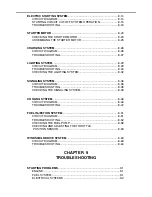
SYMBOLS
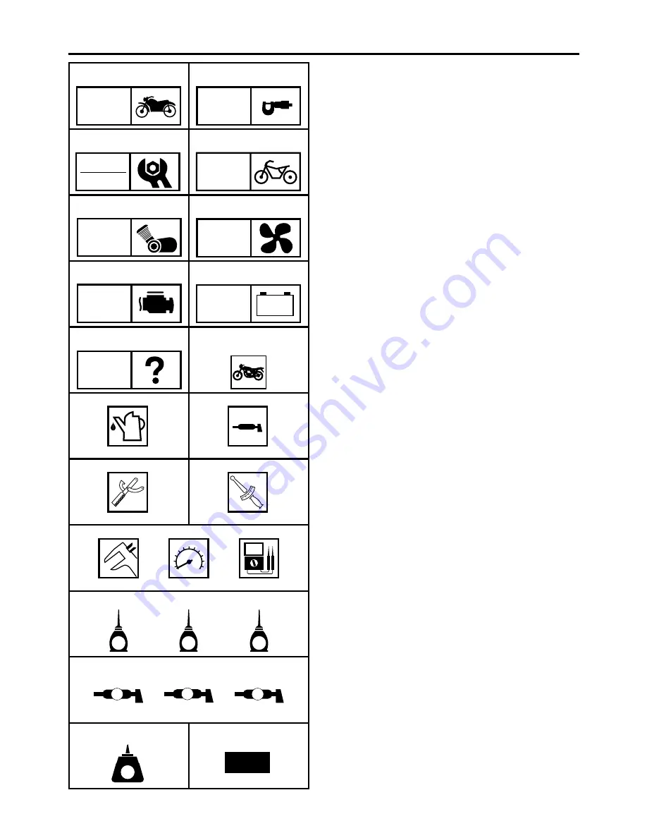
The following symbols are not relevant to
every vehicle.
Symbols
1
to
9
indicate the subject of each
chapter.
1
General information
2
Specifications
3
Periodic checks and adjustments
4
Chassis
5
Engine
6
Cooling system
7
Fuel injection system
8
Electrical system
9
Troubleshooting
Symbols
0
to
G
indicate the following.
0
Serviceable with engine mounted
A
Filling fluid
B
Lubricant
C
Special tool
D
Tightening torque
E
Wear limit, clearance
F
Engine speed
G
Electrical data
Symbols
H
to
M
in the exploded diagrams
indicate the types of lubricants and lubrication
points.
H
Engine oil
I
Gear oil
J
Molybdenum disulfide oil
K
Wheel bearing grease
L
Lithium soap base grease
M
Molybdenum disulfide grease
Symbols
N
to
O
in the exploded diagrams
indicate the following.
N
Apply locking agent (LOCTITE
®
)
O
Replace the part
1
2
3
4
5
6
7
8
9
0
A
B
C
D
E
F
G
H
I
J
K
L
M
N
O
GEN
INFO
SPEC
CHK
ADJ
CHAS
ENG
COOL
FI
–
+
ELEC
TRBL
SHTG
T
R
.
.
E
G
M
B
LS
M
LT
New
Содержание FJR1300
Страница 1: ...LIT 11616 16 18 5JW 28197 10 FJR1300R FJR1300RC SERVICE MANUAL ...
Страница 6: ......
Страница 82: ...2 22 SPEC TIGHTENING TORQUES Cylinder head tightening sequence Crankcase tightening sequence ...
Страница 89: ...2 29 SPEC 1 Crankshaft 2 Main axle 3 Drive axle OIL FLOW DIAGRAMS ...
Страница 90: ...2 30 SPEC 1 Oil nozzle 2 Main gallery bolt 3 Crankshaft OIL FLOW DIAGRAMS ...
Страница 91: ...2 31 SPEC 1 Main axle 2 Drive axle 3 Oil delivery pipe OIL FLOW DIAGRAMS ...
Страница 92: ...2 32 SPEC 1 Exhaust camshaft 2 Oil check bolt 3 Intake camshaft OIL FLOW DIAGRAMS ...
Страница 93: ...2 33 SPEC 1 Oil check bolt 2 Crankshaft 3 Oil cooler 4 Oil pump 5 Oil strainer 6 Oil pipe OIL FLOW DIAGRAMS ...
Страница 94: ...2 34 SPEC 1 Crank pin 2 Crankshaft OIL FLOW DIAGRAMS ...
Страница 95: ...2 35 SPEC 1 Rear balancer 2 Oil delivery pipe 3 Crankshaft 4 Front balancer 5 Crank pin OIL FLOW DIAGRAMS ...
Страница 97: ...2 37 SPEC 1 Main axle 2 Drive axle 3 Middle drive shaft OIL FLOW DIAGRAMS ...
Страница 98: ...2 38 SPEC COOLING SYSTEM DIAGRAMS 1 Radiator COOLING SYSTEM DIAGRAMS ...
Страница 99: ...2 39 SPEC 1 Water jacket joint 2 Oil cooler COOLING SYSTEM DIAGRAMS ...
Страница 100: ...2 40 SPEC 1 Thermostat assembly 2 Coolant reservoir 3 Radiator 4 Oil cooler COOLING SYSTEM DIAGRAMS ...
Страница 101: ...2 41 SPEC 1 Coolant reservoir 2 Radiator 3 Water pump COOLING SYSTEM DIAGRAMS ...
Страница 107: ...2 47 SPEC CABLE ROUTING 1 Tail brake light lead ...
Страница 196: ...3 80 CHK ADJ ADJUSTING THE HEADLIGHT BEAMS ...
Страница 288: ...4 92 CHAS 3 Install bearing 1 to the swingarm Installed depth a 4 0 mm 0 16 in SWINGARM ...
Страница 531: ...8 35 ELEC LIGHTING SYSTEM ...
Страница 570: ......
Страница 571: ...YAMAHA MOTOR CO LTD 2500 SHINGAI IWATA SHIZUOKA JAPAN PRINTED IN U S A ...


