1 - 7
GEN
INFO
FEATURES
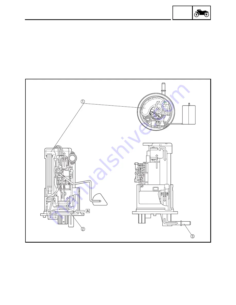
Fuel pump
The fuel pump, which is mounted in the fuel tank, draws the fuel directly from the tank and pumps it
to the injector.
A filter that is provided in the fuel pump prevents any debris in the fuel tank from entering the fuel
system downstream of the pump.
The pump consists of a pump unit, electric motor, filter, and valves.
The pump unit is a Wesco type rotary pump that is connected to the motor shaft.
A relief valve is provided to prevent the fuel pressure from rising abnormally if the fuel hose
becomes clogged. This valve opens when the fuel pressure at the discharge outlet reaches
between 440 and 640 kpa, and returns the fuel to the fuel tank.
1
Fuel filter
2
Fuel inlet strainer
3
Outlet
È
Fuel
Содержание FJR1300
Страница 1: ...LIT 11616 16 18 5JW 28197 10 FJR1300R FJR1300RC SERVICE MANUAL ...
Страница 6: ......
Страница 82: ...2 22 SPEC TIGHTENING TORQUES Cylinder head tightening sequence Crankcase tightening sequence ...
Страница 89: ...2 29 SPEC 1 Crankshaft 2 Main axle 3 Drive axle OIL FLOW DIAGRAMS ...
Страница 90: ...2 30 SPEC 1 Oil nozzle 2 Main gallery bolt 3 Crankshaft OIL FLOW DIAGRAMS ...
Страница 91: ...2 31 SPEC 1 Main axle 2 Drive axle 3 Oil delivery pipe OIL FLOW DIAGRAMS ...
Страница 92: ...2 32 SPEC 1 Exhaust camshaft 2 Oil check bolt 3 Intake camshaft OIL FLOW DIAGRAMS ...
Страница 93: ...2 33 SPEC 1 Oil check bolt 2 Crankshaft 3 Oil cooler 4 Oil pump 5 Oil strainer 6 Oil pipe OIL FLOW DIAGRAMS ...
Страница 94: ...2 34 SPEC 1 Crank pin 2 Crankshaft OIL FLOW DIAGRAMS ...
Страница 95: ...2 35 SPEC 1 Rear balancer 2 Oil delivery pipe 3 Crankshaft 4 Front balancer 5 Crank pin OIL FLOW DIAGRAMS ...
Страница 97: ...2 37 SPEC 1 Main axle 2 Drive axle 3 Middle drive shaft OIL FLOW DIAGRAMS ...
Страница 98: ...2 38 SPEC COOLING SYSTEM DIAGRAMS 1 Radiator COOLING SYSTEM DIAGRAMS ...
Страница 99: ...2 39 SPEC 1 Water jacket joint 2 Oil cooler COOLING SYSTEM DIAGRAMS ...
Страница 100: ...2 40 SPEC 1 Thermostat assembly 2 Coolant reservoir 3 Radiator 4 Oil cooler COOLING SYSTEM DIAGRAMS ...
Страница 101: ...2 41 SPEC 1 Coolant reservoir 2 Radiator 3 Water pump COOLING SYSTEM DIAGRAMS ...
Страница 107: ...2 47 SPEC CABLE ROUTING 1 Tail brake light lead ...
Страница 196: ...3 80 CHK ADJ ADJUSTING THE HEADLIGHT BEAMS ...
Страница 288: ...4 92 CHAS 3 Install bearing 1 to the swingarm Installed depth a 4 0 mm 0 16 in SWINGARM ...
Страница 531: ...8 35 ELEC LIGHTING SYSTEM ...
Страница 570: ......
Страница 571: ...YAMAHA MOTOR CO LTD 2500 SHINGAI IWATA SHIZUOKA JAPAN PRINTED IN U S A ...


