3-
25
3
I/O INTERF
ACE
3-7 I/O Assignment Change Function
3-7-2 I/O signal descripion
The meaning of each signal is explained below.
■
Point number designation inputs 0 to 5 (PI0 to PI5)
These inputs designate the point number of the target position where the robot moves with a
point movement command (ABS-PT, INC-PT). (For details on the ABS-PT and INC-PT
commands, see 3.2.1, "Dedicated command input" in this chapter.)
These inputs are also used to designate the point number of the target position where point data
is written with a point data write command (PSET).
The point number of the target position must be specified before running a point movement
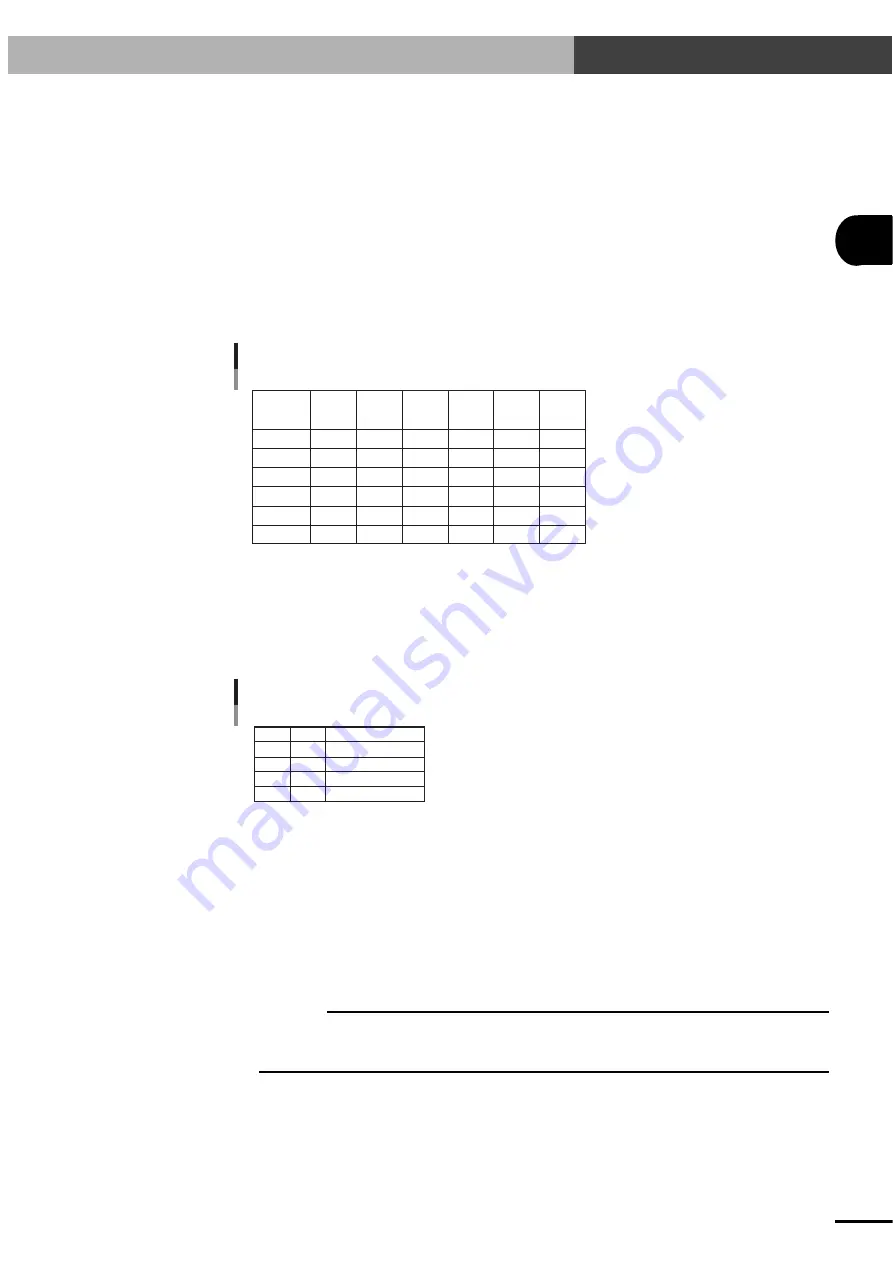
command or point write command. The point number is specified by a binary code. See the
table below to specify each point number.
Point number designation example
PI5
(2
5
)
PI No.
Point No.
P0
P1
P7
P15
P31
P63
OFF
OFF
OFF
OFF
OFF
ON
PI4
(2
4
)
OFF
OFF
OFF
OFF
ON
ON
PI3
(2
3
)
OFF
OFF
OFF
ON
ON
ON
PI2
(2
2
)
OFF
OFF
ON
ON
ON
ON
PI1
(2
1
)
OFF
OFF
ON
ON
ON
ON
PI0
(2
0
)
OFF
ON
ON
ON
ON
ON
■
Movement speed setting (SPD1, SPD2)
Designates the speed at which the robot moves with a point movement command (ABS-PT,
INC-PT) or jog movement command (JOG+, JOG-). (For details on the ABS-PT and INC-PT
commands, see 3.2.1, "Dedicated command input" in this chapter.)
The movement speed must be specified before running a point movement command or jog
movement command. See the table below to specify the movement speed.
Movement speed setting example
SPD2 SPD1
OFF
ON
OFF
ON
Movement speed
100%
PRM5
PRM6
PRM7
OFF
OFF
ON
ON
■
Jog movement (+ direction) command (JOG+)
Moves the robot in jog mode along the + (plus) direction.
The robot moves in jog mode along the + (plus) direction as long as this signal is on. The
movement speed is 100mm/sec.
This speed can be changed by using SPD1 and SPD2. In this case, the movement speed is given
by the following equation.
Movement speed [mm/sec] = 100
×
(Movement speed [%] specified with SPD1 and SPD2) / 100
In jog mode the robot usually moves along the X-axis. However, the Y-axis can be specified
with DI13 and DI14 (pin No. B11 and A12) by enabling PRM10 (Control axis selection with I/
O command). (Refer to "PRM10: Control axis selection with I/O command".)
c
CAUTION
• If the CHG (mode switch input) signal is switched during jog movement, the robot comes to an error stop.
• When specifying the axis, the DI13 and DI14 (pin No. B11 and A12) status must be checked beforehand.(Refer
to the Jog movement (JOG+, JOG-) timing chart in "3-7-3 Timing chart".)
Artisan Technology Group - Quality Instrumentation ... Guaranteed | (888) 88-SOURCE | www.artisantg.com
Содержание DRCX
Страница 3: ...Artisan Technology Group Quality Instrumentation Guaranteed 888 88 SOURCE www artisantg com ...
Страница 9: ...vi MEMO Artisan Technology Group Quality Instrumentation Guaranteed 888 88 SOURCE www artisantg com ...
Страница 129: ...7 12 MEMO Artisan Technology Group Quality Instrumentation Guaranteed 888 88 SOURCE www artisantg com ...
Страница 207: ...9 16 MEMO Artisan Technology Group Quality Instrumentation Guaranteed 888 88 SOURCE www artisantg com ...
Страница 233: ...10 26 MEMO Artisan Technology Group Quality Instrumentation Guaranteed 888 88 SOURCE www artisantg com ...
Страница 281: ...12 10 MEMO Artisan Technology Group Quality Instrumentation Guaranteed 888 88 SOURCE www artisantg com ...
Страница 310: ...MEMO Artisan Technology Group Quality Instrumentation Guaranteed 888 88 SOURCE www artisantg com ...


