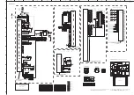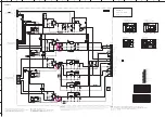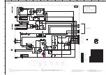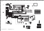
CB90
1
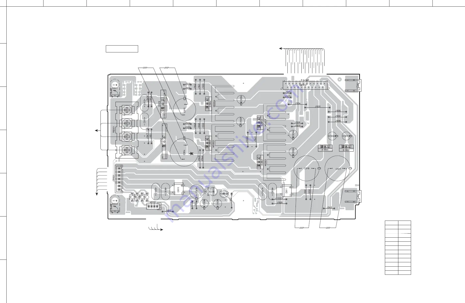
W902
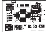
FRONT (1)
(Side A)
+7MT
+7MT
MT_GND
MT_GND
+5MO1
+5MO1
MO_GND
MO_GND
+5MO2
+5MO2
NC
NC
PRVD
FL_PON
+5D
+5D
+5D
DGND
DGND
DGND
+12RY
-12RY
RY_GND
FLGND
+VP
ACFL1
ACFL2
BR
GR
RE
BL
to POWER TRANSFORMER
(for DIGITAL/FRONT P.C.B.)
to POWER TRANSFORMER
(for DIGITAL/FRONT P.C.B.)
GND
OUT
Vcc
GND
OUT
Vcc
GND
OUT
Vcc
GND
OUT
Vcc
COM
OUT
IN
COM
OUT
IN
5 k-ohms
10 W
5 k-ohms
10 W
5 k-ohms
10 W
5 k-ohms
10 W
A
B
C
D
E
F
G
H
I
J
1
2
3
4
5
6
7
54
CD-S3000
Safety measures
• Some internal parts in this product contain high voltages and are dangerous. Be sure to take safety measures during servicing, such
as wearing insulating gloves.
• Note that the capacitors indicated below are dangerous even after the power is turned off because an electric charge remains and a
high voltage continues to exist there. Before starting any repair work, connect a discharging resistor (5 k-ohms/10 W) to the terminals
of each capacitor indicated below to discharge electricity. The time required for discharging is about 30 seconds per each.
C914–C917 on FRONT (1) P.C.B.
安全対策
・ この製品の内部には高電圧部分があり危険です。修理の際は、絶縁性の手袋を使用するなどの安全対策を行ってください。
・ 下記のコンデンサには電源を OFF にした後も電荷が残り、高電圧が維持されており危険です。修理作業前に放電用抵抗
(5 k Ω /10 W)を下記の各コンデンサの端子間に接続して放電してください。放電所用時間は各々約 30 秒間です。
FRONT(1)P.C.B. の C914~C917
Ref no. Location
D910
E5
D911
G5
D912
D4
D913
D3
IC901
G4
IC902
E4
IC903
G5
IC904
E3
IC905
H4
IC906
H4
Q901
E5
Q902
F5
• Semiconductor Location
Содержание CD-S3000
Страница 6: ... FRONT PANELS U K A B G L V J models T model 6 CD S3000 CD S3000 ...
Страница 7: ... REAR PANELS U V models U model V model Bottom view 7 CD S3000 CD S3000 ...
Страница 8: ...A B G L models K model T model A model B G models 8 CD S3000 CD S3000 ...
Страница 9: ...J model 9 CD S3000 CD S3000 ...
Страница 86: ...86 CD S3000 CD S3000 ...
Страница 87: ...MEMO 87 CD S3000 CD S3000 87 ...
Страница 88: ...CD S3000 ...


