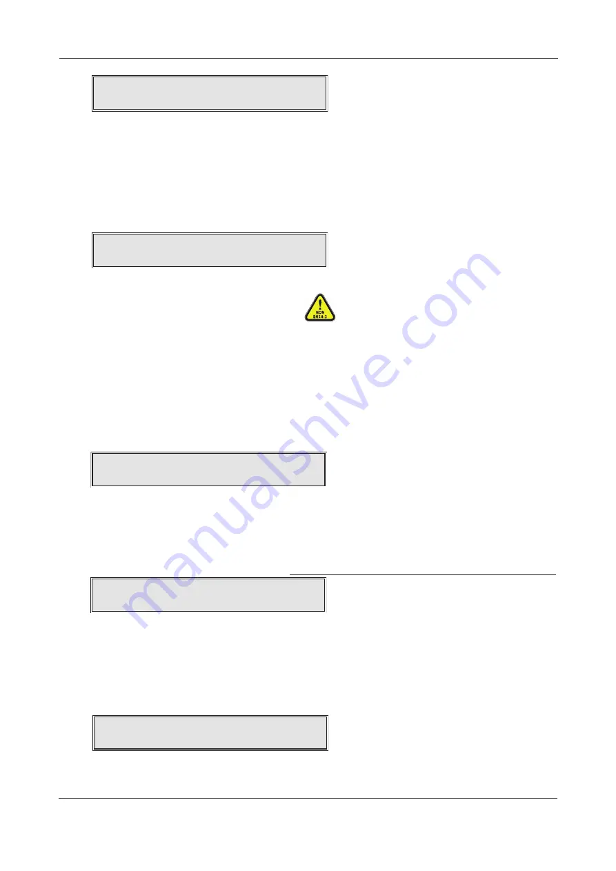
Enter the code again by pressing the
5
(1)
4
(2)
6
(3)
3
(4) buttons in same sequence. If the two codes match,
the new code will be accepted and you will be taken back into Access Level 3. If you type an incorrect
confirmation code you will be prompted to start the code entry sequence again. The same process can be
used to change access level 3 code. BE SURE TO KEEP A RECORD OF ANY CHANGED CODES FOR FUTURE USE.
Connect to PC
This function allows you to activate the panel’s PC connection for system programming purposes. ALL of the
panel’s cause and effect programming, device and zone naming, zone dependency functions, etc., must be
carried out using our separately PC programming software tools (XFP507). When the CONNECT TO PC
?
prompt appears, press the Accept
4
button. If all connections are correct, the following message will appear:
If there is a problem with the panel to PC connection, this will be flagged at the PC when you try to
upload or download any site specific data.
Network functions (optional)
Selecting this menu option takes you to the network functions submenu where you can configure the
panel to be part of a non-redundant network of up to eight XFP main panels, OR allow it to have up to
eight XFP repeaters connected to it. This option is only available if you have a network communication
card fitted at the panel (see pages 12 & 13 for a detailed overview of main panel networking and
repeater panel connection). The network functions submenu has three options - SET COMMS FUNC-
TION, SET PANEL NUMBER and SET PANEL FITTED. Other options, such as what events and what level
of control is allowed between networked panels is implemented using the panel’s PC programming
software tools.
SET COMMS FUNCTION
This function allows you to set the panel’s RS485 comms to operate in Network or Repeater mode.
When selected, press the Accept
4
button and a message similar to the one below will appear:
Use the
5
and
6
buttons to scroll between Repeater and Network and press the Accept
4
button as
appropriate. The panel’s flash database will update and you will be returned to the Network Functions submenu.
SET PANEL NUMBER
If networking XFP main panels, this function allows you to give the panel a unique ID number (1-8) so it can
be recognised by other panels on the network. Note that Repeaters do not need to be assigned an ID number.
When selected, press the Accept
4
button and a message similar to the one below will appear:
Use the
5
and
6
buttons to scroll to the desired number and press the Accept
4
button to select it.
The panel’s flash database will update and you will be returned to the Network Functions submenu.
SET PANEL FITTED
This function allows you to turn off the fault monitoring of other networked XFP main panels. Typically used if
maintenance work is to be carried out at a networked panel to temporarily prevent integrity faults being
flagged. When selected, press the Accept
4
button and a message similar to the one below will appear:
Use the
5
and
6
buttons to scroll to the desired networked panel and press the Accept
4
button to accept
it. The panel’s flash database will update and you will be returned to the Network Functions submenu.
Remember to reverse the function when maintenance work is complete.
XFP ENGINEERING MANUAL • Approved Document No. DFU1200510 Rev 3 • Page 20 of 36
XFP 16 ZONE ANALOGUE ADDRESSABLE FIRE ALARM PANEL
S
ET PANEL NUMBER:1
NETWORK PANEL:1
Enter NEW A
cc
ess Level 2
c
o
d
e:****
C
onfirm New A
cc
ess Level 2
c
o
d
e:
P
C
c
onne
c
te
d
...
Press E
SC
to
d
is
c
onne
c
t from P
C
C
OMM
S
I
S
S
ET FOR: REPEATER
Note: The XFP network and XFP repeaters have
not been assessed to EN54-2.


