background image


6

Using the Fiery X12/Fiery X40 Advanced Controller Interface Kit


T


O


REASSEMBLE


THE


 F


IERY 


X12/F


IERY 


X40


1.

Reseat all boards, cables, connectors, and other parts loosened or removed during 
inspection or service.

2.

Place the Fiery X12/Fiery X40 in its standard operating position.

3.

Place the side panel onto the Fiery X12/Fiery X40 so the grooves on the bottom of the 
side panel fit into the grooves in the tray. 


Be careful not to damage any ribbon cables; if necessary, fold the ribbon cables inside the 
tray before replacing the side panel.


4.

Close the side panel. Two clips on the top edge of the panel will click when it is properly 
installed.

5.

Replace the screw that secures the side panel.

N


OTE


:


 Do not leave the Fiery X12/Fiery X40 side panel off after servicing. An airflow 

channel is created by the side panel and the fan. Leaving the Fiery X12/Fiery X40 open 
could reduce the operational life expectancy of internal Fiery X12/Fiery X40 
components.


6.

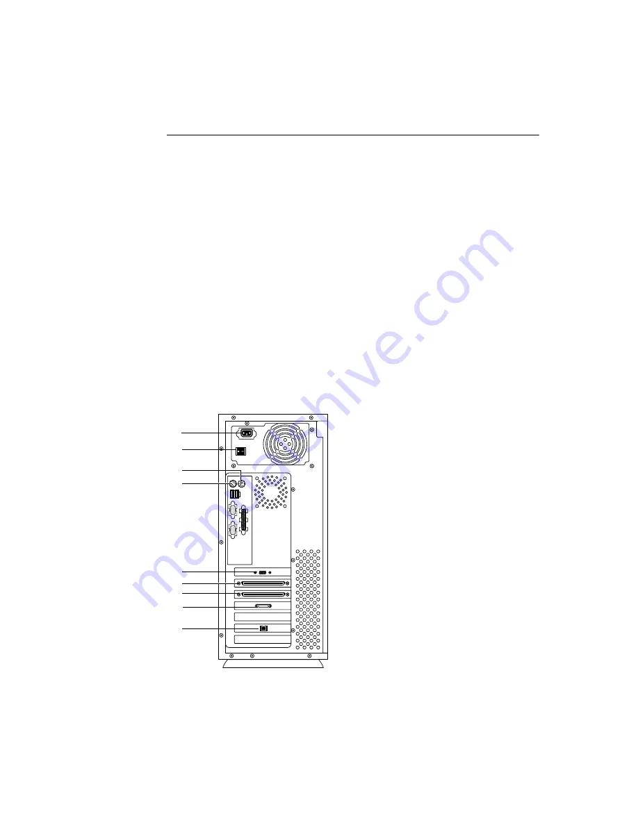
Connect any cables removed during service to the back of the Fiery X12/Fiery X40.

7.

Connect the monitor, keyboard, and mouse to the back of the Fiery X12/Fiery X40.

8.

Connect the monitor power cable to the back of the monitor (some monitors may already 
have this cable attached). 

Keyboard

10/100BaseT

Power switch

Power connector

Monitor

Copier interface (scan)

Mouse

Copier interface (print)

(not used)

Содержание DOCUCOLOR 12

Страница 1: ...USING TH E F I ER Y X 12 FIER Y X40 AD VAN C ED CONTRO LLER I N T ER F ACE K I T Part Number 4501XXXX...

Страница 2: ......

Страница 3: ...nd Typefaces reproduced therefrom Trademarks and d assign your rights under this Agreement to a transferee of all of your right title and interest in and to Fiery X12 provided the transferee agrees to...

Страница 4: ...S 252 227 7013 or in subparagraphs c 1 and 2 of the Commercial Computer Software Restricted Right Clause at 48 CFR 52 227 19 as applicable Third Party Beneficiary You are hereby notified that Adobe Sy...

Страница 5: ...OS chip includes an additional socket mount in case pins are bent during installation Monitor keyboard and mouse provided separately In order to use this kit you need to Access the Service menu and se...

Страница 6: ...the Fiery X12 Fiery X40 is running the startup diagnostics hold down the fourth line selection button on the Control Panel to access the Service menu If you do not press the fourth line selection but...

Страница 7: ...isplayed indicating it is now safe to power off the system and replace the BIOS chip with the one provided in this kit 5 At the following screen power off the Fiery X12 Fiery X40 using the power switc...

Страница 8: ...low 3 Grasp the side panel at the top on both sides and gently pull it away from the tray 4 Lift off the side panel 5 The Fiery X12 Fiery X40 internal components are now accessible Attach an ESD wrist...

Страница 9: ...ard 3 Insert the BIOS chip provided in this kit into the socket so that the notch in the chip is aligned with the notch in the socket The BIOS chip is shipped in a socket mount that helps prevent pins...

Страница 10: ...n the top edge of the panel will click when it is properly installed 5 Replace the screw that secures the side panel NOTE Do not leave the Fiery X12 Fiery X40 side panel off after servicing An airflow...

Страница 11: ...ce the Control Panel screen indicates that the upgrade is complete press any key on the Control Panel to reboot the system If the screen indicates that the system was not upgraded check to make sure y...

Страница 12: ......

Отзывы: