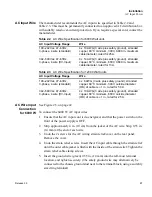

Installation
Load Connections
Release 3.0
51
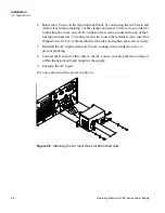
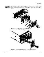
Single Load
To connect a single load to the DC output bus bars (10–150V outputs):
1. Ensure that the power supply is powered OFF.
2. Place a bolt in the connecting hole of the negative bus bar, and fasten the
negative wire or bus bar, a washer, and a nut to the bolt.
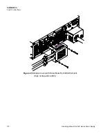
3. Using a wrench, turn the bolt until it is secure at approximately 25 foot-pounds
(34Nm).
4. Fasten the positive wire or bus bar to the positive bus, using a bolt, washer, and
nut.
5. Tighten the bolt to approximately 25 foot-pounds (34Nm).
6. Ensure that the positive and negative wires are arranged so bare wires do not
come into contact with each other or the chassis.
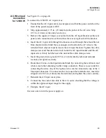
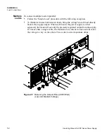
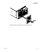
To connect the DC output wire clamp connectors (300V, 600V outputs):
•
Connect appropriately sized wires as described in steps 1 to 6 above, except strip
0.5 in. (14mm) of insulation off each load wire, and clamp in the output
connector by securely tightening the vertical clamp screw for each output.
Содержание XDC
Страница 2: ......
Страница 3: ...Operating Manual for XDC 6000 Watt and 12000 Watt Series Digital Programmable DC Power Supply ...
Страница 22: ...List of Figures xx Operating Manual for XDC Series Power Supply ...
Страница 34: ...About The XDC Power Supply Overview of Operation 32 Operating Manual for XDC Series Power Supply ...
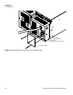
Страница 57: ...Installation Load Connections Release 3 0 55 Figure 2 11Output for 12000 Watt units High Voltage 300 600V ...
Страница 174: ...Remote Operation SCPI Commands for Digital Interfaces 172 Operating Manual for XDC Series Power Supply ...
Страница 180: ...Current Sharing 6000 Watt only Operation 178 Operating Manual for XDC Series Power Supply ...
Страница 216: ...SCPI Command Reference Expressions 214 Operating Manual for XDC Series Power Supply ...
Страница 228: ...GPIB Performance Specifications 226 Operating Manual for XDC Series Power Supply ...
Страница 253: ......