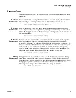


SCPI Com
m
an
d Refer
ence
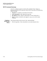
SCPI Co
mmand Summary
Release 3.0
20
3
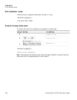
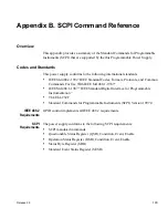
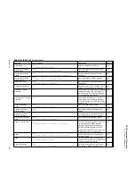
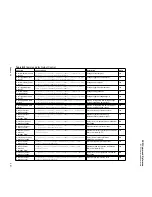
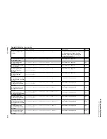
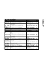
Table B.5
Commands for Calibration
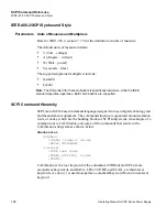
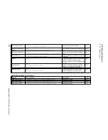
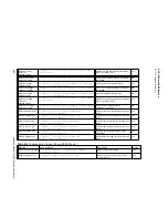
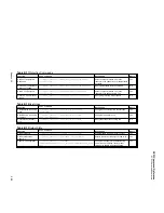
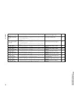
Table B.6
Command to Clear all Protection Mechanisms
Function
SCPI Command
Description
Query
Restore Factory
ion
[:]CALibration[<channel>]:RESTore
Restonres the calibration to the constants set
at the factory
N/A
Change Calibration
Password
[:]CALibration[<channel>][:SECure]:CODE <codeword>
Changes the calibration security code.
No
Set Calibration State
[:]CALibration[<channel>][:SECure]:STATe
<on-off-state>,<codeword>
Change calibration state (mode)
Yes
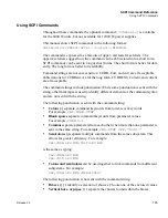
Set Analog Current
Programming Input Level
[:]CALibration[<channel>]:ANALog:<5V|10V>:PROGram:CURRe
nt:LEVel {MINimum|MAXimum}
Set analog programming current calibration
level
No
Enter Analog Current
Programming Input Data
[:]CALibration[<channel>]:ANALog:
:{5V|10V}:PROGram:CURRent[:DATA] <current>
Set analog programming current calibration
data
No
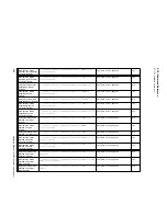
Set Analog Voltage
Programming Input Level
[:]CALibration[<channel>]:ANALog:
:{5V|10V}:PROGram:VOLTage:LEVel {MINimum|MAXimum}
Set analog programming voltage calibration
level
No
Enter Analog Voltage
Programming Input Data
[:]CALibration[<channel>]:ANALog:
:{5V|10V}:PROGram:VOLTage[:DATA] <current>
Set analog programming voltage calibration
data
No
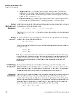
Set Analog Current
Readback Output Level
[:]CALibration[<channel>]:ANALog:
:{5V|10V}:READback:CURRent:LEVel {MINimum|MAXimum}
Set analog readback current calibration level
No
Enter Analog Current
Readback Output Data
[:]CALibration[<channel>]:ANALog:
:{5V|10V}:READback:CURRent[:DATA] <current>
Set analog readback current calibration data
No
Set Analog Voltage
Readback Output Level
[:]CALibration[<channel>]:ANALog:
:{5V|10V}:READback:VOLTage:LEVel {MINimum|MAXimum}
Set analog readback voltage calibration level No
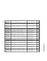
Enter Analog Voltage
Readback Output Data
[:]CALibration[<channel>]:ANALog:
:{5V|10V}:READback:VOLTage[:DATA] <current>
Set analog readback voltage calibration data
No
Set Supply Output Current
Level
[:]CALibration[<channel>]:OUTPut:CURRent:LEVel
{MINimum|MAXimum}
Set output current calibration level
No
Enter Output Current Data
[:]CALibration[<channel>]:OUTPut:CURRent[:DATA]
<current>
Set output current calibration data
No
Set Supply Output Voltage
Level
[:]CALibration[<channel>]:OUTPut:VOLTage:LEVel
{MINimum|MAXimum}
Set voltage output calibration level
No
Enter Output Voltage Data
[:]CALibration[<channel>]:OUTPut:VOLTage[:DATA]
<voltage>
Set voltage output calibration data
No
Function
SCPI Command
Description
Query
Clear Output Protection
[:]OUTPut[<channel>]:PROTection:CLEar
Clears the protection mechanism.
N/A
Содержание XDC
Страница 2: ......
Страница 3: ...Operating Manual for XDC 6000 Watt and 12000 Watt Series Digital Programmable DC Power Supply ...
Страница 22: ...List of Figures xx Operating Manual for XDC Series Power Supply ...
Страница 34: ...About The XDC Power Supply Overview of Operation 32 Operating Manual for XDC Series Power Supply ...
Страница 57: ...Installation Load Connections Release 3 0 55 Figure 2 11Output for 12000 Watt units High Voltage 300 600V ...
Страница 174: ...Remote Operation SCPI Commands for Digital Interfaces 172 Operating Manual for XDC Series Power Supply ...
Страница 180: ...Current Sharing 6000 Watt only Operation 178 Operating Manual for XDC Series Power Supply ...
Страница 216: ...SCPI Command Reference Expressions 214 Operating Manual for XDC Series Power Supply ...
Страница 228: ...GPIB Performance Specifications 226 Operating Manual for XDC Series Power Supply ...
Страница 253: ......