Page: 14
SmartPad LCD
© 2003 Xantech Corporation
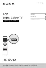
WALL
CUT-OUT WALL TEMPLATE
CUTTING TOOL
Figure 5 – Cutting Mounting Hole
4. After the four areas are cut out, remove the Cutting-Hole Template and carefully remove the four areas
that remain attached. Clean the area of any loose pieces still making sure not to enlarge the hole past
the recommended dimensions.
5. Remove the appropriate hole-knockouts on the back box to allow for wiring of the SPLCD display.
Cable Access
Punch-Outs
Figure 6 – Back Box Cable Access Point (Back-Box Rear View)
6. Bring cable through wall and desired punch-out access hole in the Back Box.
7. Insert Back Box into the wall and carefully hold in evenly place as to not allow it to fall into the wall.
8. Insert the Mounting Clip
into SLOT ‘A’ and ‘B’ as shown in Detail ‘A’ of
Figure 7
.
9.
Push the Clip with your thumb in the direction of the arrow. The back of the clip should move down into
SLOT ‘B’.
Note
: If more pressure is needed, use a screw driver as shown in Detail ‘B’ of
Figure 7
10.
Repeat for all four clips. A rear view of the Back Box with clips installed is shown below.