INSTALLATION & PROGRAMMING MANUAL
SMARTPAD LCD
™
TOUCH-SCREEN PANEL CONTROLLER
Models SPLCD39G, SPLCD57G, SPLCD64G & SPLCD64V
New Feature Addendum Included
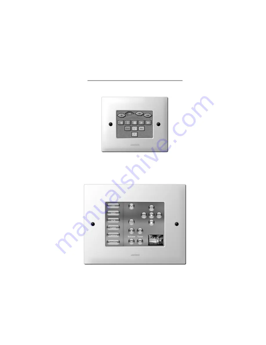
SPLCD39G
SPLCD64V
Страница 1: ...INSTALLATION PROGRAMMING MANUAL SMARTPAD LCD TOUCH SCREEN PANEL CONTROLLER Models SPLCD39G SPLCD57G SPLCD64G SPLCD64V New Feature Addendum Included SPLCD39G SPLCD64V...
Страница 2: ...n For example the appliance should not be situated on a bed sofa rug or similar surface that may block the ventilation openings or placed in a built in installation such as a bookcase or cabinet that...
Страница 3: ...ring 18 IR In Zone 18 INSTALLING SPLCD INTO BACK BOX 19 SECTION 3 MAINTENANCE CALIBRATION 20 CALIBRATION 20 TOUCH SENSE CALIBRATION 20 MAINTENANCE 20 CLEANING 20 SECTION 4 PROGRAMMING THE SMARTPAD LCD...
Страница 4: ...RO S 38 SELECTING IR PALETTES FROM THE IR CODE LIBRARY 38 SELECTING IR PALETTES 38 SELECTING RS232 COMMAND PALETTES 38 ASSOCIATING COMMANDS TO GTL S DRAG AND DROP COMMANDS 38 Programming Sequences Mac...
Страница 5: ...s RS232 Input 52 SECTION 7 APPENDIX 53 INTERFACING SPLCD WITH MRC44 MRC88 IR CONTROL 53 PROGRAMMING SPLCD FOR USE WITH MRC44 ZONE CONTROL 53 PROGRAMMING SPLCD FOR USE WITH MRC88 ZONE CONTROL 54 SMARTP...
Страница 6: ...options This keypad is also directly compatible with Xantech s MRC88 products for seamless integration with the Whole house Audio Video Entertainment system The SmartPad LCD Touch Screen Panel Keypad...
Страница 7: ...USB Port Program cables and software included DragSPLCD is used to graphically design your screens and assign IR and or RS232 Macros An internal IR Library is also included for ease of programming The...
Страница 8: ...iver for pass through of IR commands from Hand Held IR Remotes TalkBack Status LED LED indicates presence of IR and or programmable STATUS indication of Zone or other user defined power on off indicat...
Страница 9: ...SmartPad LCD PANEL AND FEATURE DESCRIPTIONS 12 4 2 6 5 7 8 10 9 11 1 3 Figure 2a SmartPad LCD Model SPLCD39G Front Panel Features and Functions 12 4 2 6 5 3 7 8 10 9 11 1 Figure 2b SmartPad LCD Model...
Страница 10: ...igger IR and or RS232 macros when RC68 IR commands are received Wide Bandwidth IR Receiver Excepts IR with carrier frequencies within the range of 32kHz and 75kHz 3 IR Talkback and Status LED Indicato...
Страница 11: ...unter clockwise to reduce brightness 11 LCD Contrast Control Adjusts Contrast of SPLCD screen Slowly turn clockwise to increase contrast of images on LCD screen 12 Bezel Mounting Clips 4 Guide clips f...
Страница 12: ...or 791 44 19 Power Input IR Output Terminal a 16VDC For connection from 16VDC SPLCD Power Supply Models SPLCDPS1 SPLCDPS4 b GND Power Supply and IR GND connection c STATUS 5 30VDC Status Input for Mac...
Страница 13: ...e size is critical as there is a 0 00 inch tolerance for this cutout It is imperative that the provided mounting template be used to assure proper hole size Check the table below to be sure you are us...
Страница 14: ...display Cable Access Punch Outs Figure 6 Back Box Cable Access Point Back Box Rear View 6 Bring cable through wall and desired punch out access hole in the Back Box 7 Insert Back Box into the wall and...
Страница 15: ...ernal IR Input and Local IR Emitter Output The following sections below address each of these wiring configurations POWER SUPPLY STANDARD XANTECH IR OUTPUT BUS WIRING Figure 3 19 A 4 Termianl WECO con...
Страница 16: ...ication of a unit or Zones power status or it can be an OUTPUT 12VDC from the SPLCD to trigger some other external device This is important to note before STATUS wiring is made between the SPLCD and t...
Страница 17: ...o fashions via this connection 1 Via IR along the dedicated IR lines of the MRC s CAT5 connection Pins 4 5 MRC88 MRC44 2 Direct to the MRC88 processor via the internal RS485 communication lines Future...
Страница 18: ...Adaptor may be necessary for proper communication Please consult manufactures specification of device being controlled DB9 Pin Out Function 2 Rx 3 Tx 5 GND RS422232 DB9 Pin Out IR IN ZONE Figure 3 18...
Страница 19: ...Box leaving slack for strain relief and connect to appropriate ports on rear of the SPLCD Display 2 Insert SPLCD into Back Box oriented according to desired viewing angle so that the unit is flush wit...
Страница 20: ...ot should appear on the side opposite the built in IR Receiver 6 With the stylus touch the center of the dot and release 7 Another calibration dot will appear towards the middle of the screen Again to...
Страница 21: ...ng Port Figure 2 7 to the DB9 COM PORT on your PC USB Programming Part No 05913660 Connects the SPLCD USB Programming Port Figure 2 9 to the PC s USB port CONNECTING THE SMARTPAD LCD TO THE PC To prog...
Страница 22: ...cans the serial ports on your computer and will display the available ports under Preferences in the File menu Unavailable ports will be grayed out CONFIGURING USB PORT To configure the USB Port for t...
Страница 23: ...and verifying a response from the SmartPad LCD you will confirm proper communication and may continue 1 Power the Unit ON and allow to boot to steady state 2 Click on the Base Unit Menu and select Who...
Страница 24: ...create stylish and intuitive screens in multiple pages for controlling any IR and or RS232 Device Once a project is created and a setup environment chosen you are automatically placed in Graphics mod...
Страница 25: ...n using the DVD menu PLACING SOURCE GTL S 1 Once the Background is placed in the Systems window click on the Sources TAB in the GRAPHICS window to display the Source buttons associated with that Style...
Страница 26: ...te You may also place a Text Label onto the Background to describe the function of a button or group of buttons This may be desired for Volume or Channel Up Down controls For more information on placi...
Страница 27: ...buttons 5 You may now insert additional pages in the same manner if so desired or place a GTL button to return to the previous page To Return to the Previous Page complete the following 6 Drag a Func...
Страница 28: ...size and font style can all be edited here to any True Type font currently installed on your PC 6 After the Font type Size and Style are selected click OK to save the settings 7 To change the Color o...
Страница 29: ...e in our database there might not be any need to teach IR commands into the system To check the Dragon Drop IR Software s extensive IR Code Library do the following 1 Make sure a SmartPAD LCD Project...
Страница 30: ...r version of Dragon Drop IR software XIR1 method CAN be copied into the SPLCD software i e palettes created in DragMRC Frag450 or Drag460 software CAN be copied and used in Dragon Drop IR SPLCD softwa...
Страница 31: ...the command the left side of the Palette Editor i e Power Play Stop etc A message stating Waiting For IR will appear This process will time out in 10 seconds 8 While continuing to keep the source remo...
Страница 32: ...and executes 5 The controlled component should respond to each command sent i e Power turns the source ON or OFF PLAY plays the content etc NOTE Only functions with the symbol will execute 6 If a comp...
Страница 33: ...required for the new component 5 Press ESC on keyboard to save and exit 6 New Brands Components and Functions can now be selected and programmed in Palette Editor GETTING SOURCE COMMANDS FROM THE INT...
Страница 34: ...to the Brand and bci files in DragMRC 17 At this point or at any later date you can choose additional component types from the CCF file e g DVD etc if listed by using the CCF Importer again Simply cli...
Страница 35: ...Functions on the left hand side and compare to the source remote If your function is not displayed or not named appropriately see the section entitled Editing Function Names in the Palette Editor 5 C...
Страница 36: ...vice being tested for the proper communication settings 4 Click on the command string to be tested on the left hand side of the RS232 Palette Editor Note Only commands with the icon will be able to be...
Страница 37: ...em as well as all future versions of Dragon Drop IR RS232 capable products Therefore the procedure of learning and testing these commands and creating the Palette file for an individual source compone...
Страница 38: ...licking the Edit Palette bar or closed with the X button in the title bar SELECTING RS232 COMMAND PALETTES 1 From the Palette Menu click SELECT RS232 COMMAND PALATTE 2 Follow steps 2 3 above under Sel...
Страница 39: ...set the number of times to repeat a code 2 Double Click in the word REPEAT This will place a cycle symbol and the words Repeat 3 Times if 3 is selected at the bottom of the Macro Command List 3 Left C...
Страница 40: ...em Test before getting into more complex system features To transfer the project to the SPLCD complete the following procedure 1 Click on BASE UNIT and select WHO AM I from the menu list Verify a vali...
Страница 41: ...s and RS232 commands This means a basic programmable remote can trigger any command IR or RS232 to communicate with all devices connected to the SPLCD A total of 55 Macro s can be triggered in this fa...
Страница 42: ...instructions 5 Repeat steps 2 thru 4 for all of the desired RC68 Trigger Commands programmed PROGRAMMING THE URC 2B P FOR USE WITH SPLCD RC68 TRIGGERED SEQUENCES Programming Xantech Model URC 2B P Bl...
Страница 43: ...ol any number of IR controlled devices This can give the ability for a central PC or other RS232 unit to control any IR device connected to the SPLCD Connecting Block Note For RS232 Communication the...
Страница 44: ...LECTING IR PALETTES 1 From the Palette menu click SELECT IR COMMAND PALETTE or press F4 on the keyboard A list of palettes file names appears to the right with Select Palette in the title bar 2 Scroll...
Страница 45: ...B SENSE TRIGGER MACRO s The STATUS line located on the rear of the SPLCD Figure 3 19c may also be utilized to trigger a Macro IR and or RS232 Two macro s can be triggered when the incoming STATUS volt...
Страница 46: ...orporation 2 Open all palettes to be used in the POWER ON macro and place the commands into the Macro Command List Window Figure 29 Sense Trigger Setup Figure 29a Intelligent Power Management ASSIGNIN...
Страница 47: ...ote The URC 2P B is pre programmed with Bank Track Codes 1 thru 8 and is directly compatible with the SPLCD Bank Track Code system Figure 30 Assigning Bank Track Codes to Source GTL s FIRMWARE UPGRADE...
Страница 48: ...conducted without having to re transfer your project to the controller It is a way of keeping your unit up to date to take advantage of new features 1 Start Dragon Drop IR SPLCD software and connect...
Страница 49: ...SPLCD Options Settings RC68 CODE GROUP The RC68 Code Group setting refers to the group of IR codes that will be used to trigger RC68 Sequences as discussed in Section 5 The number associated with thi...
Страница 50: ...e page currently selected The default Bank Track Code Group is D8 STATUS LED SETTINGS The Status LED Figure 2 3 can be configured to track the STATUS line on the rear of the SPLCD Figure 3 19C If this...
Страница 51: ...Screen Drop or Lift via a 12VDC Trigger or turn on a remote amplifier Note The STATUS output is rated at 15mA maximum BACKLIGHT CONTROL Set the Backlight to stay ON for a specified amount of time afte...
Страница 52: ...o change Baud Rate Data Bits Stop Bits or Parity settings click on the corresponding to access the drop down menu and click on the desired setting Default settings for all are shown above in Figure 34...
Страница 53: ...C68 Command Palette Hit F5 on the Keyboard 6 Select the OPTIONS TAB on the RC68 Command Window 7 Under MODEL select MRC44 and verify the Code Group setting is the same as that of the MRC44 Default Cod...
Страница 54: ...36 9 Select INPUT 1 on the RC68 00 Button and verify the proper command description is shown in the Macro Command List Window 10 Repeat for all Source Input GTL s 11 Add a Source GTL and Label for OFF...
Страница 55: ...SmartPad LCD Page 55 2003 Xantech Corporation Figure 37a MRC88 Toggle Power Programming Figure 37b SPLCD MRC88 Zone Toggle Power Programming...
Страница 56: ...tware version shall be noted at the top of the pop up window If it is not noted or the version does not read 1 2 0 or higher please see www xantech com and download the latest version of Dragon Drop I...
Страница 57: ...L to be placed on the video screen during Full Screen Video mode or any screen desired This is extremely useful for Music Server Control with feedback display on units that output a Video Menu theme w...
Страница 58: ...er Integration To interface to a Music Server Video Menu Screen or any other products Video Menu Screen follow the steps below If the product interfacing to has a BMP bitmap file for reference you can...
Страница 59: ...CD Controllers SPLCD39G 57G 64G and 64V Transparent GTL s can be placed anywhere over an object such as a picture used as a backdrop Volume Bars etc See the example below illustrating how Transparent...
Страница 60: ...roller port on the rear of the SPLCD Panel 2 16Vdc Power must still be run directly to the 16VDC and GND Terminals on the rear of the SPLCD panel Note The SPLCD cannot be powered directly from the MRC...
Страница 61: ...o buttons within the MRC88 Controller Whatever Macro is programmed within the MRC88 under these buttons the SPLCD can now execute these Macro s 5 Scroll through the list and associate SPLCD buttons to...
Страница 62: ...ical Bars Vertical Bar for Volume display or EQ Balance display To display one or more of these objects 1 Right click on a blank area of the background 2 Select Insert MRC88 Object from the drop down...
Страница 63: ...and select Zone Volume Command 5 Select the Zone in this case Zone 1 6 Select the 80 button on the Virtual RC68 or any other free RC68 Trigger button 7 Select a discrete Volume Level for the LOW setti...
Страница 64: ...1 Click on Palettes and select RC68 Command Palette from the menu 2 Click on the OPTIONS Tab on the Virtual RC68 Palette and choose MRC88 from the Xantech Model drop down menu 3 Click on the PALETTE...
Страница 65: ...map Image 3 Place the image into the desired Style Background folder Note Background Style Directories are located at C Program Files Xantech Dragon Drop IR SPLCD Icons SPLCD folder as shown below 4 R...
Страница 66: ...Page 66 SmartPad LCD 2003 Xantech Corporation XANTECH CORPORATIOIN 12950 Bradley Avenue Sylmar CA 91342 3829 phone 818 362 0353 fax 818 362 9506 www xantech com Part No 08901480 Rev B 10 28 04...