background image

630140_1


XFIRE_1200_GB_Manual_R

emotion


100mm MAX

Flue Diam.

203mm

2.0


Creating the Cavity: 


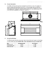
The dimensioned drawing below shows the size of opening that must be created to fit the 


XFIRE 1200. The wall directly above the fire should be finished / clad / lined after the fire 


has been installed, unless there is an access hatch or the chase is open to the ceiling 


cavity, which allows the flue to be installed after the wall has been lined.  


 Note: 

It is not necessary to line or vent the cavity, and it may be constructed with timber. 


3.0


Hearth and Floor Clearances: 


There should be at least 100mm between the bottom of the XFIRE 1200 and any horizontal 


surface below, for example hearths and floors.  


3.1


Wall and Cabinet Clearances: 


There must be a minimum of 100mm from the sides of the facia to any protruding side 


walls or cabinetry.


4.0


Wall Linings:  


The wall board that lines the outside of this opening can be normal dry wall 


(Plaster Board) and does not need to be non-combustible providing that it does not come 


any closer to the fire than the dimensions shown in section 2.0. 

Note: 

The temperature of 


the wall lining directly above the heater does get warm and hence may discolour paint 


finishes that are susceptible to temperature damage or distort vinyl wall coverings.  


5.0


Television Positioning Considerations: 


It is becoming common practice for consumers to mount flat screen TV’s above their gas 

 fireplace. 


Most TV manufacturers have specified in their instructions that the TV should not be 


installed on, near or above a heat source. For this reason TV location decisions rest solely 


with the householder and Escea will not be held liable for any adverse affects on a TV 


located near to an Escea fireplace that may be caused by heat.  


The drawings overleaf are suggestions that may be used as a GUIDE for those consumers 


who do decide to locate their TV above an XFIRE 1200 gas fire. These drawings show 


ways to reduce the amount of warm air rising off the fireplace and onto the TV 


The


wall


and


framework


in


front


of


the


flue


must


not


exceed


100mm


in


thickness,


this


includes


plaster


board


or


any


wall


linings.


This


is


to


ensure


there


is


at


least


25mm


gap


between


all


fluing


components


and


any


combustible


material.

Содержание 1200 Limestone

Страница 1: ...Fires INSTALLATION USERS INSTRUCTIONS PRODUCT CODES XT LIM X FIRE 1200 Limestone XT GRA X FIRE 1200 Granite XT TRA X FIRE 1200 Travertine LEAVE WITH THE USER Acquisitions of London 24 Holmes Road Lon...

Страница 2: ...a Registered Installer This appliance is for use on Natural Gas G20 at a supply pressure of 20mbar or Propane G31 at a supply pressure of 37mbar In IE consult document I S 813 1996 Domestic Gas Insta...

Страница 3: ...ese instructions fully before proceeding with the installation Leave unpacking and installation of the stone frame facia until the fireplace has been commissioned to avoid damage to the facia panels R...

Страница 4: ...arranty Installation Installation must be carried out by a registered installer who on completion of the installation must issue a certificate of compliance in accordance with national and or local co...

Страница 5: ...remote The glass on the front of the appliance is considered a working surface and as such care should be taken not to touch this while the appliance is running as it will get hot 1 1 Energy Input Rat...

Страница 6: ...ny closer to the fire than the dimensions shown in section 2 0 Note The temperature of the wall lining directly above the heater does get warm and hence may discolour paint finishes that are susceptib...

Страница 7: ...onsibility to satisfy themselves that their TV mounting and mantle design will not exceed the listed maximum operating temperature of their electronic goods 5 1 Combustible Mantle Clearances The diagr...

Страница 8: ...the shaded area 6 0 Corner Installations If a cavity is to be created in a corner the following drawing gives the minimum sizes 7 0 Laying Gas Pipe Gas pipe should be sized as per the requirements of...

Страница 9: ...ans of an 8mm diameter compression fitting An accessible inline isolation or service valve should also be fitted The regulator that is supplied with the fire MUST NOT BE REMOVED Removal of the regulat...

Страница 10: ...the right Note It may be necessary to use washers on the fasteners to securely fasten the fire to the wall When fixing the fireplace in position ensure that you leave a gap between the fireplace flan...

Страница 11: ...equirements of BS 5440 1 Then use Appendix A to work out the quantities of the flue components that are required 12 1 Any offsets in your flue configuration should be 45 where possible 12 2 If your fl...

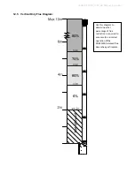
Страница 12: ...B_Manual_R emotion 12 5 Vertical Only Flue Diagram Use this diagram to determine what percentage of flue restriction is required to ensure safe and correct operation of the XFIRE1200 balanced flue dec...

Страница 13: ...al_R emotion 12 6 Horizontally Terminating Flue Diagram Use this diagram to determine what percentage of flue restriction is required to ensure safe and correct operation of the XFIRE1200 balanced flu...

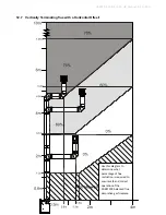
Страница 14: ...otion 12 7 Vertically Terminating flue with a Horizontal Offset Use this diagram to determine what percentage of flue restriction is required to ensure safe and correct operation of the XFIRE1200 bala...

Страница 15: ...FIRE_1200_GB_Manual_R emotion 12 8 Standard Flueing Configurations The following flue components are available from your SpecFlue UK FreeFone 0800 9020220 International 44 1787 880333 in kitset form D...

Страница 16: ...630140_1 XFIRE_1200_GB_Manual_R emotion 12 9 Locating the Flue Terminal The flue terminal must be located using the information given in the following excerpts from BS 5440 1...

Страница 17: ...630140_1 XFIRE_1200_GB_Manual_R emotion...

Страница 18: ...630140_1 XFIRE_1200_GB_Manual_R emotion...

Страница 19: ...A In addition for temperature and structural reasons the terminal should not be nearer than 150mm fanned draught or 300mm natural draught to an opening in the building fabric formed for the purpose o...

Страница 20: ...alant is required to seal the Terminal Cap to the external wall A bead should be run along the edge of the Terminal that will be in contact with the wall once installed 12 12 Twist locking procedure B...

Страница 21: ...elf not the facia When using horizontal flue runs vertical measurements should be measured to the centre line of the horizontal flue pipes When using 90 elbows in the installation use the diagram belo...

Страница 22: ...ted and using a Phillips Pozi Drive screwdriver remove the two screws located inside the firebox as shown Once the two screws are removed the baffle will be free to slide down and out as pictured Ensu...

Страница 23: ...and replace it with the No 46 pilot jet supplied in the kit Replace pilot line Adjust the Primary Aeration Collar on the burner to the Propane position as shown in the diagram below then place the bu...

Страница 24: ...200_GB_Manual_R emotion Finally put the sticker supplied in the conversion kit in onto the dataplate of the ST900 in the position shown The sticker must be signed and dated by the installer who has co...

Страница 25: ...ebox ensuring there are no stones or driftwood pieces inside the pilot flame surround guard Arrange the supplied driftwood pieces exactly as shown in the diagram and photo below Underneath each piece...

Страница 26: ...If pressure does not fall within the pressure tolerances listed on the table below then the installation pipe size or upstream regulator settings are incorrect If the correct supply pressure cannot be...

Страница 27: ...fire for a minimum of 20 minutes and finally assemble and fit the facia 18 2 Fitting the stone frame Take care when handling the facia and get help if necessary The Facia Brackets have been fastened...

Страница 28: ...the facia so that the hooks are above the receptacles and let it drop down into position until it is secure and free from movement Remove all protective plastic and packaging material before operating...

Страница 29: ...using a matching tile grout The limestone frame may be sealed with an appropriate stone sealer consult the retailer This will give some protection against staining such as red wine tea or coffee but...

Страница 30: ...eries which are supplied in the same packaging as the remote The remote control is supplied with a wall mount cradle the installer should mount this at a location determined by the customer 19 3 Switc...

Страница 31: ...tom row and appear indicating that the flame level can by changed by just pressing the left or middle button There are four possible flame positions Pilot flame Low flame Medium flame and High flame P...

Страница 32: ...eek s is current to remain r nabled To FF button f on configu e a Daily m ram In the erent progr switched o nu Adjus Daily and day Saturd The by pressin bar displa by showin ch hour of en To access ss...

Страница 33: ...the lower centre of the fire The touch pad features the basic operations of the fire On off and manual adjustment of the flame height To turn on the XFIRE 1200 push the ON OFF button on the touch pad...

Страница 34: ...button off becomes on Once the pairing is on there are 20 seconds to push press and release the button S1 yellow in the control unit Once this operation is done you hear a beep in the control unit an...

Страница 35: ...elect No Fan System This option enables or disables the fan system To enable it select Yes To disable it select No Soft start this option causes the thermostat mode to work incrementally When the chan...

Страница 36: ...ses as the residual gas in the burner burns away These are normal and should be no cause for concern Unit Body Firebox Different types and thicknesses of steel will expand and contract at different ra...

Страница 37: ...ture verified 15 minutes after start up 4 Ensure the pilot frame is clearly visible and free from loose material coals or gravel 5 After Plaster Board installation run fire on high for 60 minutes with...

Страница 38: ...Limited Warranty period shall be covered by this Limited Warranty for a period of three 3 months from the date of completion of the repair or for the remainder of the overall Limited Warranty period...

Страница 39: ...630140_1 XFIRE_1200_GB _Service_R emotion...

Страница 40: ...630140_1 XFIRE_1200_GB _Service_R emotion...

Страница 41: ...Check gas installation Open gas valve Valve cable disconnected or broken Connect valve cable correctly ODS cable disconnected or broken Connect correctly or replace ODS cable Pilot ignites but doesn...

Страница 42: ...est point screw Leak test all test points and gas system joins unions Check that the pilot flame correctly impinges on the flame failure device thermocouples should not glow red as this indicates that...

Страница 43: ...blocking burner ports 10 0 Inspect Flue System if possible If you have access to the flue system inspect it for damage or potential blockages including the cowl Ensure each flue component is twist lo...

Страница 44: ...hed fully home This may require substantial force A click should be felt Other components on the control tray can be replaced when necessary while tray is separate from the fireplace When replacing th...

Страница 45: ...he left side of the burner upwards and sliding the burner off the jet on the right hand side You will also need to remove the Pilot Cover The long grill at the front of the firebox in order to access...

Страница 46: ...ia has cooled before attempting to remove it The facia attaches to the fire by four hooks To remove the facia simply lift it upwards 15 20mm and pull towards you Care should always be taken when handl...

Страница 47: ...ts 4 0 Remove Control Tray if required 5 0 SERVICE Check glass assembly 6 0 Clean pilot and main burner jet 7 0 Clean burner thermocouple 8 0 Paint firebox if required 9 0 Inspect flue system if possi...

Страница 48: ...y service operation should be carried out only by a suitably qualified and trained person Gas supply MUST be isolated before any service operation is carried out on this appliance DISTRIBUTED BY Acqui...

Отзывы: