background image

24

Technical support: [email protected]     EMEA/ROW: +44 (0) 1793 230 343

ADV
ANCED OPERA

TION VIA PC SOFTW

ARE

iv. Monitor Function Menu

Monitor mode allows the status and stability of HDMI signal from connected devices to be monitored unmanned over a predefined 

period of time by using an algorithm to compare current frame image data with previous frame image data. Results are displayed in 

binary form for each time slot within the set range, allocating a ‘0’ (zero) if no signal change is detected and ‘1’ to denote a signal 

change occurred within a particular time slot.

Once set-up, Monitor mode enables signals to be accurately analyzed on-site without installer presence to maximize time/cost 

efficiency. 

NOTE:  Monitor mode requires the Analyzer to be connected to a PC with the software running.

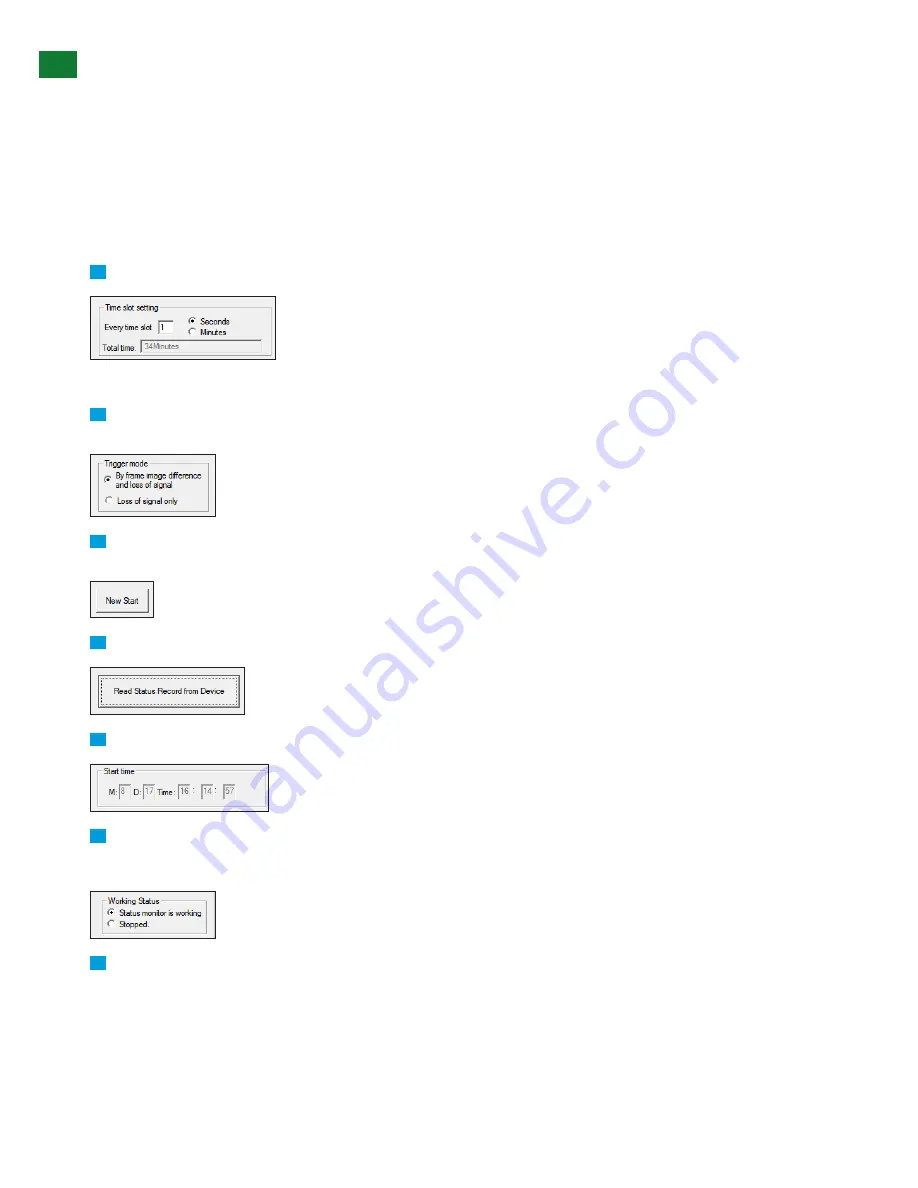
To start a new Monitoring session:

1

  Set the period of time the monitoring session should run and frequency of analysis during that selected time (Time slot).


NOTE:  Maximum number of Time slots is 2040, with each Time slot able to be set to 1-255 seconds or minutes.


2

  Set method of trigger, i.e. when the software should report an ‘event’ - whether event set to detect differences in frame image and 

signal loss, or signal loss only.

3

  After selecting the Time slot and Trigger, click ‘New Start’ to begin monitoring the incoming signal. The monitoring time shown in 

the ‘Total time’ section.

4

  Press to read data accumulated from monitoring session, with results displayed by slot in the results text box below.

5

  If desired, schedule a start date and time for a future unmanned monitoring session to be carried out (optional)

6

  Working Status - Displays the live status of monitoring period.  

-  ‘Working’ illustrates the session is ongoing

-  ‘Stopped’ indicates the session has finished

7

  Text box displays monitored results in binary form for each time slot within the set range. 


‘0’ (zero)


Illustrates a unit of time passing without an ‘event’ detected. The majority of monitoring sessions will typically 


feedback ‘0” to indicate normal operation. 

‘1’ 


Denotes an ‘event’ has been detected at that specific point in time as per set trigger criteria (potential issue). See 


session results above.

Содержание TT-KIT-4K

Страница 1: ...280 WYRE 9973 Thank you for choosing this WyreStorm product Please read these instructions carefully before installing to avoid complications later Instruction Manual TT KIT 4K 4K Test Kit Comprising...

Страница 2: ...and heed all warnings 3 Do not expose this apparatus to rain moisture sprays drips or splashes and ensure that no objects containing liquids are placed on the apparatus including cups glasses and vase...

Страница 3: ...ations Basic Setup and Operation On Screen Menu i TT GEN 4K Timing Signal Generator ii TT SIG 4K Source Signal Analyzer Advanced Operation via PC software TT GEN 4K 4K Timing Signal Generator i Genera...

Страница 4: ...to test a signal over a defined period of time enabling the installer to leave the device unmanned all day night to analyze every minute hour of use for an invaluable time and cost saving method of t...

Страница 5: ...ergy efficient 2 inch OLED screen to display signal data with on screen user interface Screen also displays video from connected device Unmanned monitor mode on enables independent assessment of signa...

Страница 6: ...t HDMI Audio Format Supported PCM only Audio Output HDMI Audio Bit 16bit 20bit 24bit Audio Sample Rate 32K 44K 48K 88K 96K 176K 192K Audio Channels Supported 8 Audio Format Supported PCM only Audio Im...

Страница 7: ...using Metal Control Front panel push button USB RS 232 Certification CE FCC RoHS Compliant Panel Description TT GEN 4K 4K Timing Signal Generator Front 1 24mm 0 95in Active Matrix OLED AMOLED screen t...

Страница 8: ...ower switch On Off 1 2 3 4 5 Panel Description TT SIG 4K 4K Source Signal Analyzer Front 1 55mm 2 2in OLED screen to displays test information menu options settings and video received connected HDMI d...

Страница 9: ...nstallation scenarios including HDMI cables installed in wall and HDMI devices such as matrices switchers splitters and displays the TT KIT 4K can also test HDMI signals distributed through HDBaseT or...

Страница 10: ...hrough a Wall Plate Using TT GEN 4K and TT SIG 4K RS 232 USB to PC RS 232 USB to PC TT SIG 4K TT GEN 4K In wall HDMI Plates KEY HDMI RS 232 USB Testing HDMI Through a Splitter Using TT GEN 4K and TT S...

Страница 11: ...ce Devices with No Display Present TT SIG 4K replaces display RS 232 USB to PC TT SIG 4K KEY HDMI RS 232 USB Testing HDMI Through HDBaseT or Similar Matrix and Receiver Note HDMI output or matrix rece...

Страница 12: ...Make sure of firm HDMI connection to devices but do not force connectors into ports Always use good quality reliable high speed Category 2 HDMI cables that support 4K within distance specification of...

Страница 13: ...o the next previous signal pattern in the menu while pressing Up Down cycles through previous next timing generation options to output Once the Generator has initialized we recommend using the Up Down...

Страница 14: ...cycle through timing settings with the details of the timing along the bottom of the screen Pressing up down buttons will cycle through the patterns retaining the last timing selected Operation of bot...

Страница 15: ...to 32k 44K 48k 88k 96k 176k 192k 7 Auto Resolution On Off 8 Audio Channel Number Auto 2ch 3ch 4ch 5ch 6ch 7ch 8ch 9 Output standby Off On Useful for simulating a power cycle of a source device when co...

Страница 16: ...no information Pressing the Menu Enter button always displays Signal Info as the first the first screen in the menu If the TT SIG 4K Source Analyzer is not receiving a signal the blue No Signal scree...

Страница 17: ...to access the full functionality of the Generator and Analyzer via a PC including the display of signal information and detailed configuration of signal parameters within their respective interfaces...

Страница 18: ...t device 9 Set desired signal parameters to be included within test conditions using the tabbed sub menus of the software TT GEN 4K Timing Signal Generator Interface A B C D E F G K L M N O H I J i Ge...

Страница 19: ...o selected user defined number E Press to read status data from the Generator and update status iii Pattern Select Menu The Pattern Select sub menu page offers a wide variety of standard and unique vi...

Страница 20: ...cted color space is fixed to RGB 4 4 4 and color depth fixed to 24bit When HDMI 2 0 4K 50 60Hz is selected color space is fixed to YUV 4 2 0 B HDCP ON OFF Allows the user to add or remove HDCP 1 4 to...

Страница 21: ...H A Click drop down options to select where to read EDID from fixed TV EDID or one of the 10 user defined save slots B Click the to read the selected EDID of connected TV screen or any previously sav...

Страница 22: ...t Serial Port number D Search Machine Click to initialize search for connected TT SIG 4K via USB or RS232 to PC E Turn On Off Output port ensure this is set to ON for the unit to pass a signal F Volum...

Страница 23: ...ew window to display signal pattern or video signals NOTE Previewing images from the source device to a PC is not recommended using RS 232 due to bandwidth limitations of the serial port approximately...

Страница 24: ...Time slots is 2040 with each Time slot able to be set to 1 255 seconds or minutes 2 Set method of trigger i e when the software should report an event whether event set to detect differences in frame...

Страница 25: ...eset EDID or 10 user defined save slots 2 Click to read EDID of connected display or any previously saved user defined EDID 3 EDID data will appear in the window to the left NOTE If no EDID appears ch...

Страница 26: ...ever possible Check unit Status LED on units are lit to indicate correct functionality NOTE Status lights for TT GEN 4K and TT SIG 4K should be static 4 Resolution If no signal reduce the resolution o...

Страница 27: ...adequate insurance and preferably in the original packaging Please include a document or letter detailing the reason for return and include a daytime telephone number and or email address where you ca...

Страница 28: ...or re install previously installed equipment travel to and from service location loss of or damage to media images data or other recorded stored content The items listed here are not exclusive but are...

Страница 29: ...INSTALLATION NOTES...

Страница 30: ...A Office Unit 22 Ergo Business Park Swindon Wiltshire SN3 3JW UK Tel 44 0 1793 230 343 WyreStorm Technical Support US 1 844 280 WYRE 9973 UK 44 0 1793 230 343 Email support wyrestorm com WyreStorm Tec...

Отзывы: