MRTALP8-DC3: #35059
Rev 8.0/1-20
10
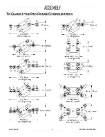
Various pad frame configurations enable the lifter to match different load dimensions and
weights. The illustrations on the preceding page show all approved configurations. Pad Spread
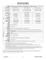
and Maximum Load Capacities are listed for a standard MRTALP811LDC3 lifter (see
“SPECIFICATIONS” on page 3 for other models).
Caution:
Connect the vacuum pads to the 2 circuits of the dual vacuum system (marked “1” and
“2” in the preceding illustrations).
1)
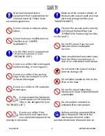
Use only approved pad
frame configurations.
Choose an approved configuration to maximize
support across the load surface and to minimize load
overhang (see “L
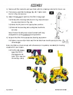
2) Install or remove the extension arms and reposition the movable pad mounts as needed
(see next page):
•
Securely position vacuum
hoses to avoid damage
during lifter operation.
To support the maximum load weight, you
must install all vacuum pads on the pad frame
and connect all vacuum hoses to the vacuum
pads, using the quick connectors (see
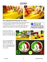
“Connecting/Disconnecting Vacuum Hoses” on page 13).
• To support larger load dimensions, you must also install all extension arms on the
pad frame.
•
Disconnecting or
removing any vacuum
pad reduces lifting capacity.
To support smaller weights and dimensions,
you may remove some extension arms or
vacuum pads, and disconnect the
corresponding vacuum hoses,
provided the
lifter still has sufficient capacity to support the load in question.
1
1..... Whenever a quick connector is disconnected, the corresponding vacuum pad does not contribute to the lifting capacity, whether or not the pad
is mounted on the pad frame.
ASSEMBLY
Содержание MRTALP810CDC3O
Страница 2: ...MRTALP8 DC3 35059 Rev 8 0 1 20 2 ...
Страница 6: ...MRTALP8 DC3 35059 Rev 8 0 1 20 4 Note A standard MRTALP811LDC3 is shown SPECIFICATIONS ...
Страница 11: ...Rev 8 0 1 20 MRTALP8 DC3 35059 9 TO CHANGE THE PAD FRAME CONFIGURATION ASSEMBLY ...
Страница 47: ...Rev 8 0 1 20 MRTALP8 DC3 35059 45 ...
Страница 48: ...MRTALP8 DC3 35059 Rev 8 0 1 20 46 ...
Страница 49: ......
Страница 50: ......


