Rev 8.0/1-20
MRTALP8-DC3: #35059
7
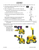
1) Remove all lifter restraints and save them with the shipping container for future use.
2)
2A
If necessary, assemble the lift bar (fig. 2A). Tighten bolts
(item 2 in fig. 2A) securely.
3) Adjust the lift point to optimize the lifter's hang angle:
3.1) Remove the retaining bolt (item 3 in fig. 2A) and loosen
the pivot bolt (item 4 if fig. 2A).
3.2) Move the lift point to the appropriate position.
3.3) Reinstall the retaining bolt and tighten both bolts
securely.
Note: Position the lift point to avoid contact with long
configurations of the pad frame during rotation.
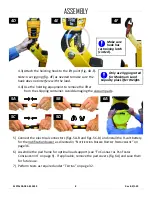
4) Suspend the lifter from appropriate hoisting equipment:
4.1) Select a crane and/or hoist rated for the Maximum Load Capacity plus the
Lifter Weight.
Note: Any lifter use must comply with all statutory or regulatory standards for hoisting
equipment in your region.
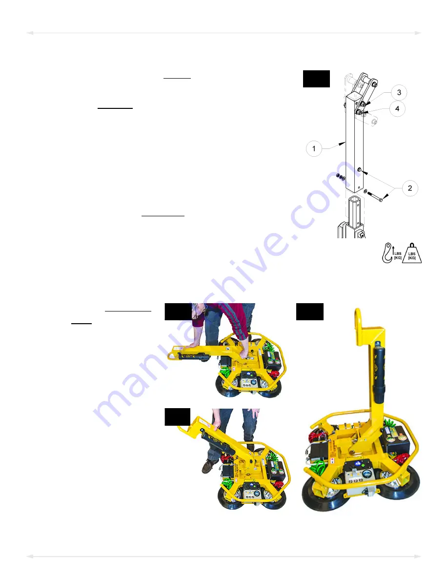
4.2)
4A
4B
4C
Pull the tilt release
lever (fig. 4A) to
disengage the tilt
latch. Then raise the
lift bar (figs. 4B-C).
ASSEMBLY
Содержание MRTALP810CDC3O
Страница 2: ...MRTALP8 DC3 35059 Rev 8 0 1 20 2 ...
Страница 6: ...MRTALP8 DC3 35059 Rev 8 0 1 20 4 Note A standard MRTALP811LDC3 is shown SPECIFICATIONS ...
Страница 11: ...Rev 8 0 1 20 MRTALP8 DC3 35059 9 TO CHANGE THE PAD FRAME CONFIGURATION ASSEMBLY ...
Страница 47: ...Rev 8 0 1 20 MRTALP8 DC3 35059 45 ...
Страница 48: ...MRTALP8 DC3 35059 Rev 8 0 1 20 46 ...
Страница 49: ......
Страница 50: ......


