background image

MRTALP8-DC3: #35059

Rev 8.0/1-20

14

INTENDED USE

L

OAD

 C

HARACTERISTICS

Do NOT lift explosives, radioactive 
substances or other hazardous materials.

Make sure the vacuum lifter is intended 
to handle each load according to these 
requirements:

•   The load weight must not exceed the Maximum Load Capacity.

•   The load must be a single piece of relatively nonporous material with a flat and 

relatively smooth contact surface.

1, 2

 To determine whether the load is too porous or 

rough, perform the “Lifter/Load Compatibility Test” on page 32.

•   The load's contact surface must be able to obtain a friction coefficient of 1 with the lifter's 

vacuum pads (see “Pad-to-Load Friction Coefficient” on page 35).  Otherwise, the 
capacity should be derated appropriately.

•   The load's surface temperature must not exceed the Operating Temperatures.

3

•   The load's 

minimum

 length and width are determined by the current Pad Spread 

(see “SPECIFICATIONS” on page 3). 

•   The load's 

maximum

 length and width are determined by its allowable overhang.

4

•   1½" [3.8 cm] is the allowable thickness at Maximum Load Capacity.

5

 The load must 

be positioned correctly on the lifter and either tilt locks or latches, if present, must 
be used when appropriate (see “OPERATION”).  If not, the allowable load thickness would 
be reduced.

6

Note: Standard vacuum pads can stain or deform load surfaces with light colors or soft coatings. 
Test such surfaces for damaging effects before using the lifter on them.

7

1..... Although concave vacuum pads can also attach to some curved loads, curvature can reduce lifting capacity.  Contact WPG for more information.

2..... A “single piece” of material includes curtainwall assemblies, unitized glazing systems and similar construction units.

3..... Vacuum pads made from a heat-resistant rubber compound can enable you to lift loads with higher surface temperatures. Contact WPG or an 

authorized dealer for more information.

4..... The allowable overhang is the amount of load material that can extend sideways beyond the vacuum pad without breaking or otherwise being 

damaged.  This depends on the load material, its thickness, and the angle of handling (if any).  Since every material has different physical 
properties, the allowable overhang must be evaluated separately for each load type.  Contact WPG or an authorized dealer for more 
information.

5..... However, the allowable thickness increases as load weight decreases.  Contact WPG for more information. 

6.....

Pad Spacers can reduce the stability of upright loads and allowable load thickness.

  Contact WPG for more information.

7..... Alternative rubber compounds are available for these purposes.  Contact WPG or an authorized dealer for more information.

Содержание MRTALP810CDC3O

Страница 1: ...l MT USA 59044 800 548 7341 phone 406 628 8231 phone 406 628 8354 fax www WPG com Record serial number in blank space above to locate see serial label on the product LOW PROFILE MANUAL ROTATOR TILTER DC VOLTAGE WITH INTELLI GRIP TECHNOLOGY Available with REMOTE CONTROL SYSTEM Model numbers MRTALP811LDC3 shown MRTALP810TDC3 MRTALP810CDC3O KEEP FOR FUTURE REFERENCE ...

Страница 2: ...MRTALP8 DC3 35059 Rev 8 0 1 20 2 ...

Страница 3: ... Taking Safety Precautions 16 Selecting a Screen Language 16 Performing Inspections and Tests 17 Checking the 12 Volt Battery 17 Preparing to Use the Remote Control System 18 TO ATTACH THE PADS TO A LOAD 19 Positioning the Lifter on the Load 19 Powering up the Lifter 20 Sealing the Pads on the Load 20 Reading the Vacuum Gauges 21 TO LIFT AND MOVE THE LOAD 22 About the Tilt Linkage 22 Interpreting ...

Страница 4: ...33 Rated Load Test 34 Remote Control System Test 34 MAINTENANCE 35 VACUUM PAD MAINTENANCE 35 Pad to Load Friction Coefficient 35 Pad Inspection 35 Pad Cleaning 36 NOTIFICATION BUZZER BATTERY REPLACEMENT 36 12 VOLT BATTERY RECHARGE 37 INTELLI GRIP DIAGNOSTIC CODES 38 TO REPLACE SEALING RING IN VPFS10T PADS 42 REPLACEMENT PARTS 43 LIMITED WARRANTY 44 TO OBTAIN REPAIRS OR WARRANTY SERVICE 44 TABLE OF...

Страница 5: ...ngle center of gravity and temperature can also affect the lifting capacity A qualified person should evaluate the effective lifting capacity for each use see definition under Rated Load Test on page 34 Per Pad 175 lbs 79 5 kg 150 lbs 68 kg 150 lbs 68 kg Total with 4 Pads 700 lbs 320 kg 600 lbs 270 kg 600 lbs 270 kg Total with 8 Pads 1 100 lbs 500 kg 1 100 lbs 500 kg 1 100 lbs 500 kg Lifter Weight...

Страница 6: ...MRTALP8 DC3 35059 Rev 8 0 1 20 4 Note A standard MRTALP811LDC3 is shown SPECIFICATIONS ...

Страница 7: ...lifter if the Maximum Load Capacity or any safety label appears to be missing or obscured Make sure the contact surfaces of the load and vacuum pads are clean before attaching the lifter see MAINTENANCE Position the vacuum pads correctly on the load before lifting see OPERATION Positioning the Lifter on the Load Do not lift a load if any vacuum indicator shows inadequate vacuum Keep unauthorized p...

Страница 8: ...ELLI GRIP CONTROL UNIT 13a POWER BUTTON 13b RELEASE BUTTON 13c ATTACH BUTTON 13d FUNCTION BUTTON 13e LCD SCREEN with BATTERY GAUGE 14 NOTIFICATION BUZZER 15 Cover for VACUUM PUMP CIRCUIT BOARD and VACUUM SENSORS 15a VACUUM LIFT LIGHT 15b STROBE LIGHT 15c VACUUM GAUGES 16 AIR FILTER 17 PAD FRAME 18 TILT RELEASE LEVER 19 VACUUM RESERVE TANKS 20 BATTERY CHARGER Note A standard MRTALP811LDC3 is shown ...

Страница 9: ...int to the appropriate position 3 3 Reinstall the retaining bolt and tighten both bolts securely Note Position the lift point to avoid contact with long configurations of the pad frame during rotation 4 Suspend the lifter from appropriate hoisting equipment 4 1 Select a crane and or hoist rated for the Maximum Load Capacity plus the Lifter Weight Note Any lifter use must comply with all statutory ...

Страница 10: ...quipment to remove the lifter from the shipping container Avoid damaging the vacuum pads 5A 5C 5B 5D 6A 5 Connect the electrical connectors figs 5A B and figs 5C D and install the 9 volt battery for the notification buzzer as directed in NOTIFICATION BUZZER BATTERY REPLACEMENT on page 36 6 Assemble the pad frame for optimal load support see TO CHANGE THE PAD FRAME CONFIGURATION on page 9 If applic...

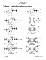
Страница 11: ...Rev 8 0 1 20 MRTALP8 DC3 35059 9 TO CHANGE THE PAD FRAME CONFIGURATION ASSEMBLY ...

Страница 12: ...sition the movable pad mounts as needed see next page Securely position vacuum hoses to avoid damage during lifter operation To support the maximum load weight you must install all vacuum pads on the pad frame and connect all vacuum hoses to the vacuum pads using the quick connectors see Connecting Disconnecting Vacuum Hoses on page 13 To support larger load dimensions you must also install all ex...

Страница 13: ...ig 2A and if necessary disconnect the vacuum hose 3 Insert the extension arm into the pad frame fig 3A 4 Insert a cotterless hitch pin to secure the extension arm fig 4A 5 Position the pad mount on the extension arm and if necessary reconnect the vacuum hose fig 5A 6 Insert a cotterless hitch pin to secure the pad mount fig 6A Notes Repeat or reverse these steps to configure the pad frame as neede...

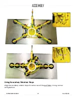
Страница 14: ...MRTALP8 DC3 35059 Rev 8 0 1 20 12 Using Secondary Rotation Stops Align the secondary rotation stops for correct use of the pad frame in long narrow configurations ASSEMBLY ...

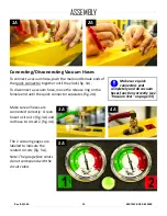
Страница 15: ... ends of the quick connector together until they lock fig 1A To disconnect a vacuum hose move the release ring on the female end until the quick connector separates fig 2A 4A 3A Make sure all hoses are connected correctly Green hose to circuit 1 fig 3A and red hose to circuit 2 fig 4A 5A The 2 vacuum gauges are labeled to indicate the related circuits fig 5A Note The gauge face colors do not corre...

Страница 16: ... the allowable load thickness would be reduced 6 Note Standard vacuum pads can stain or deform load surfaces with light colors or soft coatings Test such surfaces for damaging effects before using the lifter on them 7 1 Although concave vacuum pads can also attach to some curved loads curvature can reduce lifting capacity Contact WPG for more information 2 A single piece of material includes curta...

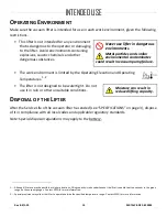
Страница 17: ...ating Temperatures 1 2 The lifter is not designed to be watertight Moisture can result in reduced lifting capacity Do not use it in rain or other unsuitable conditions DISPOSAL OF THE LIFTER After the Service Life of the vacuum lifter has ended see SPECIFICATIONS on page 3 dispose of it in compliance with all local codes and applicable regulatory standards Note Special disposal regulations may app...

Страница 18: ...tory standards for lifter operation in your region Follow trade association guidelines about precautions needed for each load material Selecting a Screen Language When the lifter is powered up for the first time the Intelli Grip control unit prompts the operator to select a language for the LCD screen Use the buttons as follows To scroll down press the release button To scroll up press the attach ...

Страница 19: ... discontinue lifter use and charge the battery see 12 VOLT BATTERY RECHARGE on page 37 If battery energy continues to decrease and you try to attach the lifter to a load the notification buzzer will sound continuously and the LCD screen will display Lockout low 12V battery along with a diagnostic code see INTELLI GRIP DIAGNOSTIC CODES on page 38 In this case you must charge the battery in order to...

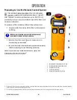
Страница 20: ...the status of the lifter and load prior to lifting Make sure nearby personnel are aware of intended remote control actions Monitor the lifter at all times to make sure it is functioning as intended 1 Be sure the load is lowered and supported correctly before releasing it see following sections Note To prevent any radio transmission press the emergency disconnect button 2 1 The Remote Control Syste...

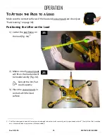
Страница 21: ...d frame on the load fig 1A 1 2 2A Make sure all vacuum pads will fit on the load and will be loaded evenly fig 2A Consult the Per Pad Load Capacity 3 Place the vacuum pads in contact with the load surface 1 The lifter is designed to handle the maximum load weight when the load s center of gravity is positioned within 2 5 cm of the lifter s rotation axis Uncentered loads may rotate or tilt unexpect...

Страница 22: ...ry and the buzzer chirps once per minute Replace the battery as needed see NOTIFICATION BUZZER BATTERY REPLACEMENT on page 36 1B To use the optional Remote Control System briefly hold the power button fig 1B on the radio transmitter to activate it 1 Keep attach function activated throughout lift Note When you hold any button on the transmitter the transmission indicator light flashes green if the ...

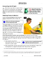
Страница 23: ... sufficient to lift the maximum load weight fig 1A Red range 16 Hg 54 kPa Vacuum level is not sufficient to lift the maximum load weight fig 1B 2 If it takes more than 5 seconds for the vacuum level to reach 5 Hg 17 kPa on either vacuum gauge press on any vacuum pad that has not yet sealed Once the pads have sealed the lifter should be able to maintain sufficient vacuum for lifting except when use...

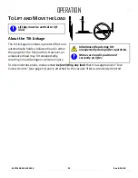
Страница 24: ...ctly on lifter The tilt linkage minimizes operator effort and automatically holds a balanced load in either the upright or the flat position However an unbalanced load may tilt unexpectedly resulting in load damage or personal injury To minimize these risks make certain before lifting any load that it has appropriate LOAD CHARACTERISTICS see page 14 and is attached to the vacuum lifter as previous...

Страница 25: ... CODES on page 38 1 Such leaks can cause the battery to be discharged more quickly If the vacuum pump is unable to overcome leakage the notification buzzer sounds continuously the lift light turns off and the LCD screen displays the message INSUFFICIENT VACUUM along with a diagnostic code see INTELLI GRIP DIAGNOSTIC CODES on page 38 If this happens 1 Stay clear of any suspended load while indicato...

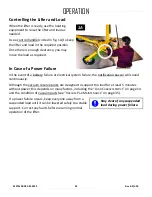
Страница 26: ...re or electrical system failure the notification buzzer will sound continuously Although the vacuum reserve tanks are designed to support the load for at least 5 minutes without power this depends on many factors including the LOAD CHARACTERISTICS on page 14 and the condition of vacuum pads see VACUUM PAD MAINTENANCE on page 35 Stay clear of any suspended load during power failure If a power failu...

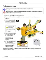
Страница 27: ...ithout contacting anyone or anything 3 3A Use the control handle inset in fig 3A to keep the load under control at all times Unbalanced loads may rotate unexpectedly when rotation latch is disengaged 4 Pull the rotation release lever circled in fig 3A to disengage the rotation latch and rotate the load as required 5 To stop load motion let go of the rotation release lever and guide the load to the...

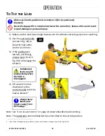
Страница 28: ...under control at all times 3 If the pad frame is latched pull the tilt release lever inset in fig 2A to disengage the tilt latch Unbalanced loads may tilt unexpectedly when tilt latch is disengaged 4 Lift upward or press downward on the control handle to tilt the load as desired 1 Always keep hands and fingers away from tilt linkage Note See LOAD CHARACTERISTICS on page 14 about allowable load ove...

Страница 29: ...RTALP8 DC3 35059 27 A load with overhang may force you to release the handle as the load approaches the flat position In this case use hand cups circled in fig 1A or other appropriate means to control the load OPERATION ...

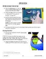
Страница 30: ... be releasing the load 2 Do not move lifter until pads release completely because such movement could result in load damage or personal injury Continue to hold the function and release buttons until the vacuum pads release the load completely Otherwise the vacuum lifter will automatically revert to attach mode 1 After the load is successfully released the lifter activates the Power Save mode autom...

Страница 31: ...es that could soil or damage vacuum pads 4 To transport the lifter secure it in the original shipping container with the original restraints or equivalent Storing the Lifter 1 1B Use the covers supplied to keep the vacuum pads clean fig 1B CE To prevent the lifter from tipping over on relatively horizontal surfaces place the vacuum pads facedown on a clean smooth flat surface Then lower the lift b...

Страница 32: ...3 3B 3D 3E 3C Disconnect the electrical connectors figs 3A B and figs 3C E to prevent battery discharge 4 Store the lifter in a clean dry location Store the battery between 32 and 70 F 0 21 C Avoid storage above 100 F 38 C 3A OPERATION ...

Страница 33: ...usual vibrations or noises while operating lifter If lifter has Remote Control System perform Remote Control System Test on page 34 Examine entire lifter for evidence of looseness excessive wear or excessive corrosion deformation cracks dents to structural or functional components cuts in vacuum pads or hoses any other hazardous conditions Inspect entire electrical system for damage wear or contam...

Страница 34: ...e strobe light flashes 6 Take precautions in case load should fall during test Raise the load a minimal distance to make sure it is supported by the lifter 7 Watch each vacuum gauge Starting from a vacuum level of 16 Hg 54 kPa the lifter must maintain a vacuum level greater than 12 Hg 41 kPa for 5 minutes 4 If not lifting this load requires additional precautions eg a load sling Contact WPG for mo...

Страница 35: ... in case load should fall during test Raise the load a minimal distance Then hold the function button and the power button for at least 5 seconds to power down the lifter 2 5 Watch the vacuum gauges The vacuum level should not decrease by more than 4 Hg 14 kPa in 5 minutes 6 Lower the load after 5 minutes or whenever a lifter fails the test and release the load as previously directed 7 Never use l...

Страница 36: ...ions 3 Vary the transmitter s direction and distance from the lifter to make sure transmissions are effective 4 If the Remote Control System is not functioning correctly the battery for the radio transmitter may need to be replaced or metal or other electrically conductive surfaces may be causing radio interference Reposition the transmitter to transmit signals effectively If the problem persists ...

Страница 37: ...erm exposure to heat chemicals or UV light can reduce the friction coefficient of vacuum pads Replace pads every 2 years or more often when necessary Pad Inspection 1A Inspect each vacuum pad fig 1A according to the INSPECTION SCHEDULE on page 31 and correct the following faults before using the lifter see REPLACEMENT PARTS when applicable Contaminates on the face 1 or sealing edges 2 Filter scree...

Страница 38: ...pad face 3 Wipe the pad face clean using a clean sponge or lint free cloth to apply the cleanser 1 4 Allow the pad to dry completely before using the lifter NOTIFICATION BUZZER BATTERY REPLACEMENT 1 Power down the lifter 2 Release the buzzer battery holder by pressing inward and sideward in the direction marked on the holder 3 3A Slide the battery tray out fig 3A 4 Install a new 9 volt battery acc...

Страница 39: ...vice recheck the battery as previously directed 1 You may use a battery charger other than the one supplied provided it is designed for 12 volt DC AGM type lead acid batteries Disconnect the battery from the vacuum generating system before charging 2 To maximize the battery s lifespan charge it promptly after each use 3 Any external power supply must conform to all applicable local codes The lifte...

Страница 40: ...lifter is powered up If so power down lifter disconnect charger from power source and power up again If code persists check battery condition as directed above B03 Charge 12V battery soon 1 chirp per minute none Charge 12 volt battery see 12 VOLT BATTERY RECHARGE on page 37 B09 Replace 9V battery 1 chirp per minute none Replace 9V battery for notification buzzer as needed see NOTIFICATION BUZZER B...

Страница 41: ...nnect connector between 12V battery and vacuum generating system Charge battery completely see 12 VOLT BATTERY RECHARGE on page 37 Then reconnect battery and try to power down again If code persists disconnect connector Service is required N04 Failed to turn controls power off 1 chirp every 2 seconds none Intelli Grip control unit failed to power down Remove 9V battery Disconnect connector between...

Страница 42: ...t available in Attach none none Operator Menus cannot be accessed while lifter is attached to load U09 Counterweight not retracted continuous on Release function is prevented because counterweight is not positioned correctly Reposition counterweight as directed see Counter Balancer OPERATING INSTRUCTIONS if necessary U10 Use POWER button for Live Stats none none Power button not function button is...

Страница 43: ...lty achieving minimum vacuum level due to high elevation In case of suspected leak check for fault s in vacuum system See relevant topics in ASSEMBLY OPERATION INSPECTIONS AND TESTS and MAINTENANCE In case of high elevation contact WPG for directions V040 Lockout vacuum sensor error continuous none Once Power Save mode is activated attach and release functions are prevented due to a vacuum sensor ...

Страница 44: ...ing into the mounting groove beginning in 4 locations as shown circled in fig 3A 4 Push gently and firmly on the outside edge of the sealing ring until the flat side fits flush against the bottom of the mounting groove fig 4A A pad ring installation tool circled in fig 4A makes this step easier see REPLACEMENT PARTS on page 43 5 Make sure the sealing ring seats securely in the mounting groove all ...

Страница 45: ... 2 Tubing Size 8 54384NC Power Lead 1 53122 Pad Fitting Elbow 5 32 ID 8 49724TT Sealing Ring Model VIFS10T2 Closed Cell Foam for VPFS10T pads 8 49724RT Sealing Ring Model VIFS10T3 Heat Resistant Rubber for VPFS10T pads 8 49672FT Vacuum Pad Model VPFS10T 10 25 cm Diameter w Replaceable Sealing Ring 8 49646T Vacuum Pad Model G3370 11 28 cm Diameter Lipped 8 49643T Vacuum Pad Model G3370 11 28 cm Dia...

Страница 46: ...l wear and tear and or the product has been damaged misused or neglected If a problem is not covered under warranty WPG will notify the customer of costs prior to repair If the customer agrees to pay all repair costs and to receive the repaired product on a C O D basis WPG then will proceed with repairs Wood s Powr Grip Co Inc 908 West Main St Laurel MT 59044 USA 406 628 8231 phone 800 548 7341 ph...

Страница 47: ...Rev 8 0 1 20 MRTALP8 DC3 35059 45 ...

Страница 48: ...MRTALP8 DC3 35059 Rev 8 0 1 20 46 ...

Страница 49: ......

Страница 50: ......

Отзывы: