


Manual 26727
VariStroke-I (VS-I) Electro-hydraulic Actuator
Woodward
42
Ensure that the linkages and couplings connecting the VS-I output
shaft to the turbine are appropriately sized and are able to withstand
the stall force and dynamic loads.
The lifting eye located on the top of the VS-I Servo Valve is intended
to lift ONLY the servo itself, not integrated servo-cylinder
configurations.
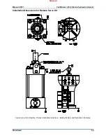
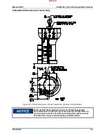
Make sure that the crane, cables, straps, and all other lifting
equipment used for VS-I lifting is able to support the VS-I weight. See
outline drawings for VS-I weights.
When transporting the Hydraulic Cylinder in an upside-down position,
the cylinder rod must be properly secured against uncontrolled rod
movement.
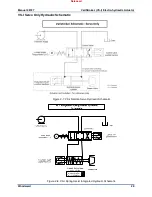
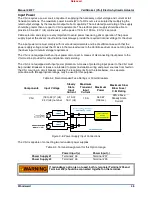
Hydraulic Connections
For the Integrated VS-I, there are two hydraulic connections that must be made to each actuator:
•
1.250 SAE J518 Code 61 Flange for Hydraulic Supply Port
•
1.500 SAE J518 Code 61 Flange for Hydraulic Drain Port
Note:
SAE J518, JIS B 8363, ISO/DIS 6162 AND DIN 20066 are interchangeable, except for bolt
sizes/threads. The VS-I uses metric bolt sizes.
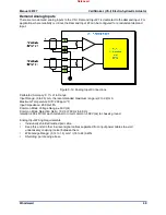
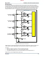
For the VS-I Remote Servo Kit and Servo Only options, there is an additional hydraulic connection
between servo and cylinder:
•
1.000 SAE J518 Code 61 Flange for Hydraulic Control Ports
Note:
SAE J518, JIS B 8363, ISO/DIS 6162 AND DIN 20066 are interchangeable, except for bolt
sizes. VS-I uses metric bolt sizes.)
•
Maximum Pipe Length between Remote Servo and Cylinder : 3 meters
Hydraulic connection tightening torques:
•
Hydraulic Supply:
4x M10x1.5 Screws Torque to (34 to 48) N·m, (25 to 35 lb-ft)
•
Hydraulic Drain:
4x M12x1.75 Screws Torque to (48 to 61) N·m, (35 to 45 lb-ft)
•
Control ports, C1 and C2 (Remote and Remote Servo):
4x M10x1.5 Screws Torque to (34 – 48) Nm, (25 - 35 lbf-ft)
•
OVBD Straight Thread port: Torque to (7 – 8) Nm, (65 - 69 lbf-in).
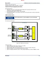
Before installing the VS-I, all hydraulic lines must be thoroughly
flushed.
Make provisions for proper filtration of the hydraulic fluid that will supply the actuator. Design the system
filtration to assure a supply of hydraulic oil with a target cleanliness level of ISO 4406 code 20/18/16 or
cleaner.
Construct the tubing connected to the actuator and/or servo to eliminate any transfer of vibration or other
forces to the actuator.
The hydraulic supply to the servo is to be 32 mm (1.25 inches) tubing capable of supplying 530 L/min
(140 US gal/min) at 34.5 bar / 500 psig.
Released


