


Manual 26727
VariStroke-I (VS-I) Electro-hydraulic Actuator
Woodward
18
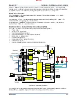
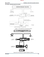
The power supply system performs the EMI filtering on the (18 to 32) V (dc) input voltage, generates
controlled voltages for several electronics sub-systems and is monitored for proper operation. If input
voltage or internal power systems are detected outside of allowable operating ranges, a diagnostic alarm
will be enunciated.
Calibration and configuration of alarms and shut down and redundancy operation are configurable via the
PC Service Tool.
The primary demand and redundant demand / feedback input signals are designed for a (4 to 20) mA
control signal. Each input signal is EMC protected.
Discrete outputs are provided for alarm and shut down enunciation. An internal LED also is illuminated
when a fault condition is detected. Cover needs to be removed to see this LED. The configurable discrete
output can be customized to output a variety of enunciations using the PC Service Tool. All of the discrete
outputs are configurable for normally open or normally closed action using the PC Service Tool.
Cylinder Position Control
The cylinder position controller adjusts the hydraulic power cylinder position to match the feedback signal
to the demand. Monitoring of both the servo position controller and cylinder position controller ensures
accurate tracking.
The position controller regulates a Pulse Width Modulated (PWM) drive signal to the actuator. The drive
current to the actuator is regulated, transiently allowing up to 10 Amps to be provided to move the
actuator at its maximum speed and torque. A steady state current limit becomes active after a period of a
few seconds to protect the actuator and electronics.
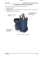
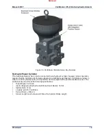
VS-I Remote Servo Only Construction
The Remote Servo (Figure 1-5) has the following major components:
1. Rotary Servo Valve
2. PCB (This information is available in the VS-I Integrated and Remote Construction section above
Rotary Servo Valve
The hydraulic servo valve has five ports: Supply, two Control Ports, Over Board Drain (OVBD), and
Drain/Tank. With the hydraulic valve in its middle position, both control ports are blocked. As the valve
rotates, supply pressure is connected to a control port while simultaneously connecting the drain to the
other control port. The combined action of the servo position controller and cylinder position controller
modulate the power cylinder position as necessary to match the input demand. OVBD is permanently
connected to drain and can (optionally) be connected to the OVBD connection on Hydraulic Power
Cylinder to drain any leakage pass the primary rod seal.
A unique function of the software is a periodic, symmetrically opposed impulse (called "Silt Buster") which
flushes silt and debris from the servo valve without causing undue wear. At the interval and amplitude
selected by the user, this function provides a very rapid motion of the hydraulic valve, allowing any silt to
be flushed to the drain passage. This motion is followed immediately by a step of equal amplitude in the
opposite direction. The opposing symmetry of the impulse results in no net change in fluid volume to the
controlled servo valve, and thus does not interrupt the control of the turbine. This unique function provides
a higher degree of stability, reliability, and silt resistance.
If the unit detects any diagnostic shut down condition, or if the detected diagnostic condition prevents
reliable control, or if a loss of power occurs, the servo valve return spring forces the valve to connect the
appropriate control pressure to drain, causing the cylinder to move to the fail-safe position.
Released


