


Manual 26727
VariStroke-I (VS-I) Electro-hydraulic Actuator
Woodward
17
If the unit detects any diagnostic shut down condition, or if the detected diagnostic condition prevents
reliable control, or if a loss of power occurs, the servo valve return spring forces the valve to connect the
appropriate control pressure to drain causing the cylinder to move to the fail-safe position.
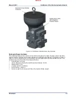
Servo Valve Actuator
The VS-I uses a rotary limited angle torque (LAT) actuator. The permanent magnet rotor is directly
coupled to the servo valve.
The position of the rotor is measured by a solid state integrated circuit on the PCB which detects the
orientation of the sensing magnet on the shaft. The
H-bridge drive is regulated by the microprocessor to precisely control the servo valve position and
maintain the cylinder stroke position demand.
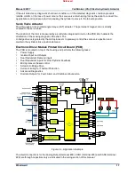
Electronic Driver Module Printed Circuit Board (PCB)
The PCB is mounted on top of the housing and performs the following tasks:
•
Power Supply
•
Isolated Input and Outputs
•
Dual Redundant Demand inputs
•
Dual Redundant inputs for Final Cylinder Feedback
•
Microprocessor based control
•
Actuator H-Bridge Drive
•
Current Limiting for Thermal Protection
•
Advanced Diagnostics
•
Discrete Outputs for Fault, Alarm and Shutdown Enunciation
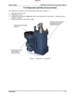
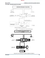
Figure 1-4. Application Example
The shield connections for the Analog Output (terminal #20), CAN1 (terminal #23) and CAN2 (terminal
#29) are through capacitors only as indicated in the wiring section of this manual.
Released


