Product Manual 26727
(Revision R, 1/2020)
Original Instructions
VariStroke-I (VS-I)
Electro-hydraulic Actuator
Installation and Operation Manual
Released
Страница 1: ...Product Manual 26727 Revision R 1 2020 Original Instructions VariStroke I VS I Electro hydraulic Actuator Installation and Operation Manual Released...
Страница 2: ...to the equipment Any such unauthorized modifications i constitute misuse and or negligence within the meaning of the product warranty thereby excluding warranty coverage for any resulting damage and i...
Страница 3: ...ng the VariStroke I Service Tool 58 Connecting to the VariStroke I 62 CHAPTER 5 CALIBRATION AND MONITORING 63 Introduction 63 System Information 63 System Information Page 65 Configuration and Calibra...
Страница 4: ...Bore Remote Servo Cylinder V45RD 15XX 115 Appendix I V45 Servo 8 inch 200mm Bore Remote Servo Cylinder V45RD 20XX 118 Appendix J V45 Servo 10 inch 250mm Bore Remote Servo Cylinder V45RD 25XX 121 Appe...
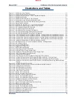
Страница 5: ...Incorrect Lifting Method 41 Figure 3 6 Suggested Configuration 43 Figure 3 7 Electrical Wiring Diagram 45 Figure 3 8 Power Supply Input Connections 46 Figure 3 9 Correct Wiring to Power Supply Input 4...
Страница 6: ...te Installation Dimensions 119 Figure I 1c V45RD 20XX Remote Installation Dimensions 120 Figure J 1a VS I Remote Maximum Allowable Distance Between Actuator and Servo 121 Figure J 1b V45RD 25XX Remote...
Страница 7: ...pecifications 23 Table 2 7 Special Ambient Temperature Specifications Allowances 25 Table 2 8 VS I Installation Drawings 31 Table 3 1 VS I Installation Bolts and Bolting Torques Recommendation 37 Tabl...
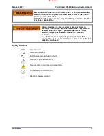
Страница 8: ...overspeed shutdown device to protect against runaway or damage to the prime mover with possible personal injury loss of life or property damage The overspeed shutdown device must be totally independe...
Страница 9: ...ing and Protection of Electronic Controls Printed Circuit Boards and Modules Follow these precautions when working with or near the control 1 Avoid the build up of static electricity on your body by n...
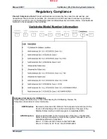
Страница 10: ...for CE Marking These listings are limited only to those units bearing the CE Marking Review the Compliance Code table for more information EMC Directive Declared to Directive 2014 30 EU of the Europe...
Страница 11: ...ents stated in Art 2 4 c and as such the product is excluded from the scope of RoHS2 EAC Customs Union These listings are limited only to those units with labels marking and manuals in Russian languag...
Страница 12: ...in width of joint L mm Comment Spool to Spacer 0 079 13 46 Sleeve to Spacer 0 079 12 85 Sleeve to Sleeve 0 048 14 76 Sleeve to Housing 0 076 15 85 Sensor to Plate 0 08 36 25 Plate to Housing 0 10 22 9...
Страница 13: ...lever les couvercles ni raccorder d brancher les prises lectriques sans vous en assurez auparavant que le syst me a bien t mis hors tension ou que vous situez bien dans une zone non explosive La subst...
Страница 14: ...nal servo valve return spring forces the actuator to a failsafe position to safely close turbine control valves upon any internal unit failure electrical input power failure position sensor failure pr...
Страница 15: ...As a way of allowing turbine control optimization the VariStroke I includes an 11 point linearization table to allow turbine OEMs or users to compensate for poor valve linearization by digitally linea...
Страница 16: ...ariStroke I is made up of the following major components Figure 1 1 1 Hydraulic Power Cylinder 2 Rotary Servo Valve 3 Feedback Sensors MLDT Magnetostrictive Linear Displacement Transducer for power cy...
Страница 17: ...iStroke I Remote Servo Kit Figure 1 2 contains the same primary components as integrated version this kit allows the Hydraulic Power Cylinder to be mounted separately from the servo in applications wh...
Страница 18: ...the other control port The combined action of the servo position controller and cylinder position controller modulate the power cylinder position as necessary to match the input demand Additionally th...
Страница 19: ...rientation of the sensing magnet on the shaft The H bridge drive is regulated by the microprocessor to precisely control the servo valve position and maintain the cylinder stroke position demand Elect...
Страница 20: ...mote Servo Only Construction The Remote Servo Figure 1 5 has the following major components 1 Rotary Servo Valve 2 PCB This information is available in the VS I Integrated and Remote Construction sect...
Страница 21: ...VariStroke Performance Equation be satisfied see Chapter 2 Performance Index In order to control cylinder position the Cylinder must be equipped with a position feedback sensor The position sensor mus...
Страница 22: ...ydraulic Actuator Woodward 20 Figure 1 6 Nomenclature and Ordering Number Encoder Note Chemically resistant versions are denoted CR in the Specials string of the VariStroke model number Please contact...
Страница 23: ...in Spring VS Bore in VS Stroke in S T U V 4 4 84 170 351 14 28 63 5 6 3 162 353 780 36 78 7 173 3 4 162 353 780 27 59 130 8 3 393 793 1578 2996 87 3 176 3 350 7 700 4 393 793 1578 3035 75 5 132 3 263...
Страница 24: ...ment damage is possible if the hydraulic connections are attached incorrectly backwards Reversed hydraulic connects will cause the actuator to operate backwards making the fail safe position opposite...
Страница 25: ...utput Signal Analog 4 20 mA Input Voltage 15 Vdc power provided by VariStroke Linearity 0 04 Full Stroke Current Drain 100 mA Sensor Length 2 times the Cylinder Stroke Length Update Rate 1 ms Sensor C...
Страница 26: ...VBD 438 20 UNF Pipe Size Between Remote Servo and Cylinder Diameter 25 4 mm 1 inch minimum Length 3 m 120 inch maximum Supply Fluid Flow Refer to following figures for Maximum Transient Flow Rate and...
Страница 27: ...h multiple features that allow hydraulic fluid to constantly flow through the servo valve and power cylinder during normal operation This allows the hydraulic fluid to act as a coolant on many of the...
Страница 28: ...se is a primary feature of the VariStroke there are limitations when paring a large servo valve with a relatively small cylinder volume Before purchasing or installing a VS I actuator the user should...
Страница 29: ...riStroke I VS I Electro hydraulic Actuator Woodward 27 Figure 2 3 Performance Chart for 4 5 and 6 Bore Actuators Diagrams Functional Block Diagram Figure 2 4 Basic Device Block Diagram without Trip Fu...
Страница 30: ...ke I VS I Electro hydraulic Actuator Woodward 28 VS I Integrated Hydraulic Schematic Figure 2 5 VS I Integrated Hydraulic Schematic VS I Remote Servo Hydraulic Schematic Figure 2 6 VS I Remote Hydraul...
Страница 31: ...VariStroke I VS I Electro hydraulic Actuator Woodward 29 VS I Servo Only Hydraulic Schematic Figure 2 7 VS I Remote Servo Hydraulic Schematic Figure 2 8 VS I Spring Assist Integrated Hydraulic Schema...
Страница 32: ...Manual 26727 VariStroke I VS I Electro hydraulic Actuator Woodward 30 Figure 2 9 VS I Spring Assist Remote Hydraulic Schematic Released...
Страница 33: ...F V45RD 12XX V45 Servo 5 inch 127mm Bore Remote Servo Cylinder G V45RD 15XX V45 Servo 6 inch 150mm Bore Remote Servo Cylinder H V45RD 20XX V45 Servo 8 inch 200mm Bore Remote Servo Cylinder I V45RD 25...
Страница 34: ...nder any orientation is acceptable b Servo valve any orientation except upside down Recommend vertical orientation 3 Service Manual Replacement Parts a Servo Valve Consult Woodward for part number b H...
Страница 35: ...ve atmosphere External fire protection is not provided in the scope of this product It is the responsibility of the user to satisfy any applicable requirements for their system Take care not to damage...
Страница 36: ...it board If the VS I actuator is to be installed in close proximity to uninsulated unshielded steam valves or piping radiation heat shields should be installed between the actuator and these hot surfa...
Страница 37: ...Manual 26727 VariStroke I VS I Electro hydraulic Actuator Woodward 35 Figure 3 1b VS I Integrated Product Installation Interface Bolting Pattern and Installation Features Released...
Страница 38: ...27 VariStroke I VS I Electro hydraulic Actuator Woodward 36 Installation Dimensions for Remote Servo Kit Figure 3 2a VS I Remote Product Installation Interface Bolting Pattern and Installation Feature...
Страница 39: ...t Grade Bolting Torque lbf ft Nm Thread Tol Class Male Female 4 100 M14x2 1 20 30 5 10 9 50 55 68 75 6H 5 127 M16x2 1 60 40 6 10 9 110 120 149 163 6H 6 152 M16x2 1 60 40 6 10 9 110 120 149 163 6H 8 20...
Страница 40: ...c Hydraulic Rod position for different cylinders versions Fail Extend Spring Assist Cylinders with no hydraulics have cylinder rod in fully extended position For all fail retract spring assist cylinde...
Страница 41: ...3 VS I Remote Servo Product Installation Interface Bolting Pattern Minimum Bolt Grade Bolting Torque and Thread Engagement Recommendation is valid for low carbon steel mounting surface to which produ...
Страница 42: ...h lifting brackets for vertical lifting When transporting use both brackets as shown below Remote Servo and Remote Cylinder have their own separate lifting features Transport both Integrated and Remot...
Страница 43: ...aintain the minimum required gap between servo valve and the actuator installation surface For reference see outline drawing Figure 3 1 Any mounting deviation from the one recommended by Woodward migh...
Страница 44: ...I Remote Servo Kit and Servo Only options there is an additional hydraulic connection between servo and cylinder 1 000 SAE J518 Code 61 Flange for Hydraulic Control Ports Note SAE J518 JIS B 8363 ISO...
Страница 45: ...of nominal value during slew step The hydraulic supply capacity should be large enough to supply the required slew rate of the attached servo system See Hydraulic Supply Specifications Significant red...
Страница 46: ...oodward 44 For step demands and or trip movements actuator may generate pressure spikes in supply line due to water hammer effect Hydraulic accumulator in supply line installed close to the VariStroke...
Страница 47: ...ng diagram Detailed wiring requirements for these connections will follow in the remainder of the Electrical Connections section The RS 232 connection is covered in Chapter 4 Installing and Running th...
Страница 48: ...e requirement The VS I is not equipped with an input power disconnect A means of disconnecting input power to the VS I must be provided for safe installation and servicing The VS I is not equipped wit...
Страница 49: ...se Wire Gauge Requirements 1 5 2 5 mm 12 16 AWG Maximum Wiring Distance 30 m Unit Grounding Ground the unit housing using the designated PE ground connection point and EMC ground connection point see...
Страница 50: ...hen bundling the field wiring inside the unit separate the unshielded power and discrete inputs outputs from the shielded analog signals Shield Installation Notes Wires exposed beyond the shield shoul...
Страница 51: ...Input Range 0 to 25 mA the recommended maximum range is 2 to 22 mA Maximum Temperature Drift 200 ppm C Input Impedance 200 10 Common Mode Voltage Range 50 V dc Common Mode Rejection Ratio 70 db 50 Hz...
Страница 52: ...C Input Impedance 235 25 Loop power 15 V 0 5 V over temperature range Max output current 200 mA total 100 mA per sensor Common Mode Voltage Range 50 V dc Common Mode Rejection Ratio 70 dB 50 Hz 60 Hz...
Страница 53: ...of Incorrect Cylinder Position Sensor Connection When Using External Power Supply When using external power supply do NOT connect it to VS I driver power outputs on the Position Feedback terminals Th...
Страница 54: ...ervice tool chapter for configuration information The design of this output is for monitoring and diagnostic purposes only and not intended for any type of closed loop feedback Figure 3 19 Analog Outp...
Страница 55: ...Figure 3 20 Discrete Inputs Connections Contact Types The inputs will accept either a dry contact from each terminal to ground or an open drain collector switch to ground Approximately 3 mA is source...
Страница 56: ...mation Wire the outputs to switch load from positive supply or switch load to ground Woodward recommends that the output be used as a high side driver as shown in the diagram below This configuration...
Страница 57: ...the wires should be kept in a twisted configuration for noise immunity CAN Communication CAN communication is not yet available in current VS I models The VS I has 2 CAN ports Figure 3 22 CAN Ports C...
Страница 58: ...meet the same hazardous locations criteria as the VS I Follow all installation recommendations and special conditions for safe use that are supplied with the cable gland The cable insulation must hav...
Страница 59: ...View diagnostic flags An unsafe condition could occur with improper use of these software tools Only trained personnel should have access to these tools The PC Service Tool or Programming and Configu...
Страница 60: ...on Clean the surface with rubbing alcohol if necessary Inspect the cover joint surfaces to ensure that they are not damaged or contaminated Installing the VariStroke I Service Tool Use the following i...
Страница 61: ...te xxx is a placeholder for the revision of the install package i e 9927 2177_NEW exe or 9927 2177_A exe are examples of Rev NEW and Rev A versions 2 The Tool launches and the Welcome screen is displa...
Страница 62: ...Installation Screen 5 The Installation of the Service tool will proceed Figure 4 5 Service Tool Installation Progress Screen 6 When the installation is finished the Installation Complete screen will a...
Страница 63: ...u connect the serial cable between the computer and the VS I the service tool will not detect the new serial connection To detect the connection you will have to exit and re launch the service tool 7...
Страница 64: ...able is connected Select your available network and then set Baud Rate to AutoDetection Press the Connect button 4 The Service Tool will connect to the VS I within a few seconds When it does the Conne...
Страница 65: ...damage to the prime mover with possible personal injury loss of life or property damage The overspeed shutdown system must be totally independent of the prime mover control system An overtemperature...
Страница 66: ...because the analog inputs are not in the 4 20 mA range or the Run Enable discrete input is selected and not on or the Shutdown button has been pressed After checking that the analog demands and the Ru...
Страница 67: ...the VS I software Servo P N S N Revision These fields display the Servo Valve Part Number S_P N Serial Number S_S N and Revision Number This information is entered automatically by the VS I software...
Страница 68: ...down Direction Fail Retracted Fail Extended This indicates the fail safe direction of the actuator Any shut down or loss of input power will result in the actuator moving in the fail safe direction Sy...
Страница 69: ...20 mA range For a list of standard Woodward position sensor lengths used in Integrated and Remote Servo Kits refer to the table shown in Chapter 7 Repair and Troubleshooting Reverse Acting The user b...
Страница 70: ...te limit when positioned within the lower 0 to 25 of the user calibrated stroke This feature provides a behavior similar to that of a conventional hydraulic cushion You may use this function to limit...
Страница 71: ...r attachments IF the linkage and or attachments CANNOT WITHSTAND THE FULL STALL FORCE of the actuator DO NOT USE FIND MINIMUM AND MAXIMUM STOPS Instead Find Minimum Stop must be used Find Minimum Stop...
Страница 72: ...ing the Cancel button will cause the Find Minimum Stop process to stop and the service tool to return to the Calibration page Find Minimum AND Maximum Stops ALL SHUTDOWNS must be cleared in order to p...
Страница 73: ...this as the maximum 20 mA demand position These limits of travel are automatically scaled to 4 mA minimum to 20 mA maximum demand levels Press the Find Minimum AND Maximum Stops button A confirmation...
Страница 74: ...settings are presented in millimeters for user convenience If a specific stroke length is required the user shall adjust these parameters while verifying the actual actuator minimum and maximum positi...
Страница 75: ...recommended The VS I can be put into manual mode by pressing the Manual Operation button The VS I can be returned to normal operation by pressing the Exit button by enabling Run Enable or by supplying...
Страница 76: ...he minimum input demand current 4 mA default that is used to position the actuator to 0 Note only after VS I shut down may values be saved Maximum Analog Demand In Indicates the maximum input demand c...
Страница 77: ...signal is supplied the actuator will operate while outputting and alarm for the other signal Feedbacks Position Feedback 1 and 2 Shows the current position of the cylinder in percent Feedback This ind...
Страница 78: ...Tool or by stepping the Analog Demand Inputs from 0 to 4 mA Output Configuration Output Configuration Page Figure 6 2 Output Configuration Screen Alarm Shutdown Discrete Outputs Alarm Shutdown Indicat...
Страница 79: ...will only be displayed when the Mode is set to Cylinder Position Low Indication Cylinder Position High Indication Sets the discrete output to energize whenever the cylinder is above the configured Ene...
Страница 80: ...d if the actuator is connected to a pilot valve to overcome sticky pilot valve action The higher the setting the higher the output shaft is oscillating amplitude It is recommended that the Dither func...
Страница 81: ...e Linearization Curve is enabled Scaled Analog Position These are the cylinder output positions steam valve position that will result when the demand is equal to the values put in to the Analog Positi...
Страница 82: ...S I Electro hydraulic Actuator Woodward 80 Figure 6 5 Alarms and Shutdowns Screen Diagnostic Values Supply Voltage Indicates the supply voltage value Internal Actuator Drive Current Indicates the actu...
Страница 83: ...active Alarm is toggled to a Shutdown the actuator will immediately shut down It is recommended that the alarm be disabled before configuring it and then re enabled when configuration is completed Ena...
Страница 84: ...s for the user s future reference These settings can also be loaded in to another VS I should the unit ever be replaced To save the VS I settings click on Settings in the ribbon at the top left of the...
Страница 85: ...odward It is recommended that all repairs and servicing of the VS I be performed by Woodward or its authorized service facilities Use of a cable gland or stopping plug that does not meet the hazardous...
Страница 86: ...Manual 26727 VariStroke I VS I Electro hydraulic Actuator Woodward 84 Figure 7 1 Shaft Seals Replacement Kits and Installation Released...
Страница 87: ...hut down of the turbine or other type of prime mover to protect against runaway or overspeed with possible personal injury loss of life or property damage EXPLOSION HAZARD Do not remove covers or conn...
Страница 88: ...Tool view the Alarms Shutdowns page to determine the fault Use the remainder of this chapter to determine the cause and solution to the fault Position Sensor Loop Power Output Overloaded Remote Servo...