SETUP
Optional XY Table Mounting
3
3-6
EGdoc101521
8.
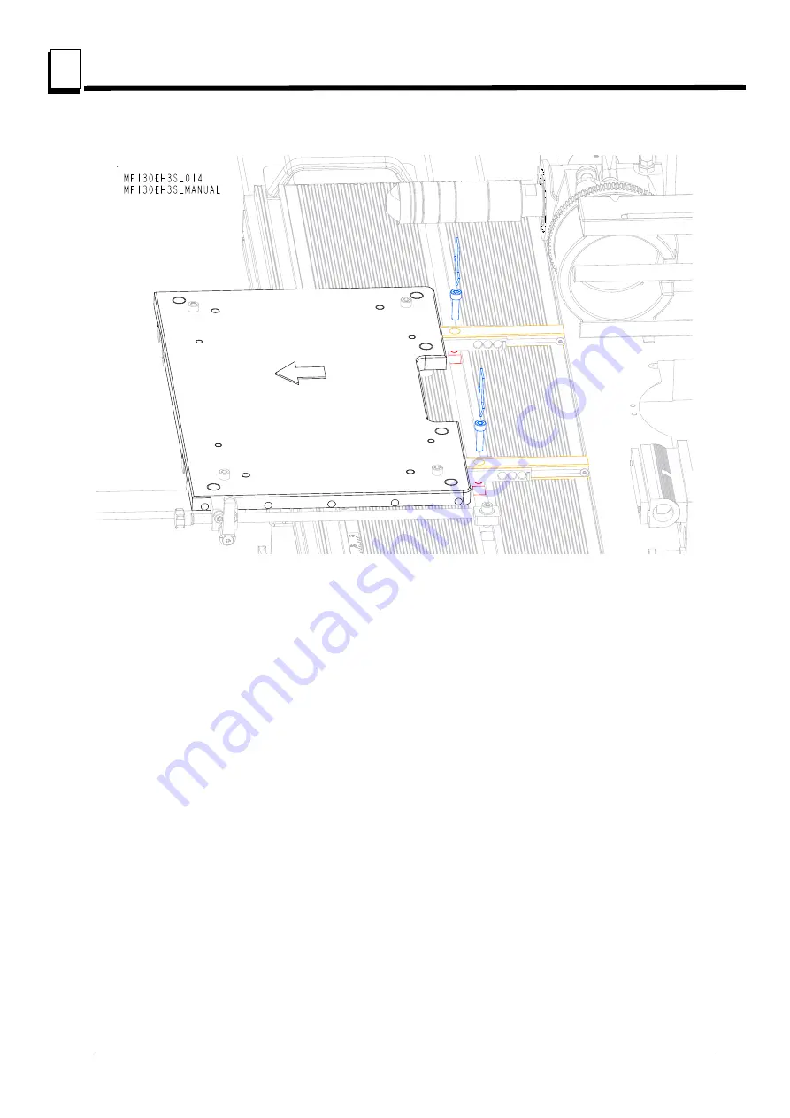
Slide the Main Working Plate to the other side to insert Bolts into the mounting plates.
FIG. 3-6
Страница 1: ......
Страница 2: ... Maintenance MF130 E3S rev A1 00 Safety is our 1 concern Read and understand all safety information and instructions before oper ating setting up or maintaining this machine Form 2502 Original Instructions Please keep for future reference ...
Страница 3: ... 3 SETUP 3 1 3 1 Optional XY Table Mounting 3 1 SECTION 4 OPERATION 4 1 4 1 Pre Operation Check 4 1 4 2 MF130 Moulder Operation 4 3 Control Panel Cutter SECTION 5 MAINTENANCE ALIGNMENT 5 1 5 1 Wear life 5 1 5 2 Sawdust Removal 5 1 5 3 Miscellaneous Maintenance 5 1 5 4 Long term storage 5 2 5 5 Safety Devices Inspection Only CE Version 5 3 SECTION 6 MF130 SPECIFICATIONS 6 1 6 1 Overall dimensions 6...
Страница 4: ...the Moulder using a forklift or a pallet jack with lifting capacity of at least 500kg When replacing the spare parts use only original parts and note that all electrical components must be assembled by a qualified electrician APPLICATIONS The Moulder can be used for sawing wood chipboard fibreboard etc The machine is intended for indoor use REQUIREMENTS The Moulder can be used in rooms with a temp...
Страница 5: ...N The machine is delivered on a pallet Due to the weight it has to be transported with auxiliary carrier equipment and in accordance with the general safety rules Check your Moulder as soon as you receive it Any transport damage must be reported to the transport company immediately Most of the machine is protected against rust but it will require extra maintenance in the form of lubrication for al...
Страница 6: ...e machine FIG 1 1 ANCHORING For the highest safety the Moulder must be anchored to the floor with 8 10 mm diameter anchor bolts TOOLS REQUIRED TO USE THE MOULDER Wrench 30 mm supplied Allen wrench 3 mm Allen wrench 4 mm Allen wrench 5 mm Allen wrench 6 mm Allen wrench 8 mm Allen wrench 10 mm Sliding calliper Meausuring tape Oil Can paraffin oil for tables Whetstone Pusher enclosed Control panel Hi...
Страница 7: ...f dust is collected indoors Poor suction is often caused by poor airflow from the chip container During work in heated rooms it is necessary to remember that the fan will quickly cool the space if the filtered air is not supplied back into the building The fire risk and dust emissions discharge must be considered because of chip collection WARNING There is a risk of fire and dust emission because ...
Страница 8: ...rs for the Moulder 100 mm 4 The pressure drop in the Moulder is 20 mm column of water at 25 m s The dust extractor airflow without external connection should be 1000 m3 h IMPORTANT The dust extractor hoses must be grounded or made of materials that do not accumulate an electrostatic charge CAUTION Always turn on the chip extractor before starting the machine ...
Страница 9: ... box with control panel Dust Duct Emergency Switch Spindle motor Spindle Locking the spindle height level Adjusting the Spindle Tilt position Adjusting the fence in sideway Adjusting the spindle side ways Sliding Table Sliding Table Fence Board Fence Adjusting the fence in sideway Board Fence Adjusting the spindle height position ...
Страница 10: ...es vital information NOTE gives helpful information Warning stripes are placed on areas where a single decal would be insufficient To avoid serious injury keep out of the path of any equipment marked with warning stripes 2 2 Safety Instructions NOTE ONLY safety instructions regarding personal injury are listed in this section Caution statements regarding machine damage appear where applicable thro...
Страница 11: ...r All Wood Mizer Moulder owners are encouraged to become thoroughly familiar with these applicable laws and comply with them fully while using the machine Wear safety clothing WARNING Secure all loose clothing and jewelry before operating this machine Failure to do so may result in serious injury or death WARNING Always wear gloves and eye protection when handling blades Changing blades is safest ...
Страница 12: ...efore operation DANGER Make sure all guards and covers are in place and secured before operating the Moulder Check that all handles screws nuts tailstocks sleeves saw blades etc are properly tightened Check that the saw blade can rotate freely and that there are no tools in or on the machine before it is started Failure to do so may result in serious injury WARNING Always shut off the motor to sto...
Страница 13: ...lure to do so may result in serious injury DANGER Always be aware of and take proper protective measures against rotating shafts pulleys fans etc Always stay a safe distance from rotating members and make sure that loose clothing or long hair do not engage rotating members resulting in possible injury WARNING Beware of rotating parts Shut down the machine and allow all moving parts to come to a co...
Страница 14: ...tion is incorrect invert the phases in the phase inverter in the power socket electrical box Setting the phases in the phase inverter correctly will ensure correct rotation directions of all motors Use proper maintenance procedures DANGER Make sure all electrical installation service and or maintenance work is performed by a qualified electrician and in accordance with applicable electrical codes ...
Страница 15: ...ts IMPORTANT Limit switch should be always in proper working condition Keep safety labels in good condition IMPORTANT Always be sure that all safety decals are clean and readable Replace all damaged safety decals to prevent personal injury or damage to the equipment Contact your local distributor or Wood Mizer Customer Service to order more decals IMPORTANT If replacing a component which has a saf...
Страница 16: ...on TABLE 2 0 Label View Label Number Description 096317 CAUTION Carefully read the operator s manual before operating the machine Observe all instructions and safety rules when operating 096316 Electric box opening is possible with the switch in 0 position only 096319 Always disconnect the power cord before opening the electric box ...
Страница 17: ...ion Safety EGdoc101521 2 8 2 099221H CAUTION Keep safe distance when the machine is working 524993 CAUTION Hand injury hazard 535402 Always wear safety goggles boots gloves and ear muffs when operating the machine TABLE 2 0 099221h ...
Страница 18: ...Safety Safety Labels Description 2 2 9 EGdoc101521 Safety S20097 Motor rotation direction P85070 CE safety certification TABLE 2 0 S20097 ...
Страница 19: ...rts List 2503 3 1 Optional XY Table Mounting 1 Slide the handles A into the Sliding Table 2 Put the Angle B under the Sliding Table between two nuts Tighten the nuts to stabilize the Angle See Figure 3 1 See Figure 3 2 3 Slide the mounting plates A and the mounting plate of the handle s rod stopper C into the Sliding Table See Figure 3 3 4 Set the plates A that they are evenly spaced between axis ...
Страница 20: ...SETUP Optional XY Table Mounting 3 3 2 EGdoc101521 5 Tighten the mounting plates using the fasteners B FIG 3 2 A B C D ...
Страница 21: ...SETUP Optional XY Table Mounting EGdoc101521 3 3 3 FIG 3 3 A D a a a a ...
Страница 22: ...SETUP Optional XY Table Mounting 3 3 4 EGdoc101521 See Figure 3 4 6 Put the Main Working Plate A on the mounting plates B See Figure 3 5 FIG 3 4 ...
Страница 23: ...SETUP Optional XY Table Mounting EGdoc101521 3 5 3 7 Slide the Main Working Plate to insert Bolts into the mounting plates See Figure 3 6 FIG 3 5 ...
Страница 24: ...SETUP Optional XY Table Mounting 3 3 6 EGdoc101521 8 Slide the Main Working Plate to the other side to insert Bolts into the mounting plates FIG 3 6 ...
Страница 25: ...SETUP Optional XY Table Mounting EGdoc101521 3 7 3 See Figure 3 7 9 Mount the Bottom Pin Bracket FIG 3 7 ...
Страница 26: ...SETUP Optional XY Table Mounting 3 3 8 EGdoc101521 See Figure 3 8 10 Mount the Rod A into the Bottom Pin Bracket B through the Bearing C FIG 3 8 A B C ...
Страница 27: ... can be operated indoors with the sawdust collection system only The MF130 Moulder must not be operated when it is raining snowing and in case of rain or snow the machine must be stored under roof or indoors The MF130 Moulder can be operated in temperatures ranging from 15oC to 40oC only The illuminance at the operator s position should be at least 300 lx1 The operator s position and E Stop button...
Страница 28: ...WARNING If the drive belt breaks wait until all rotating parts are completely stopped Failure to do so may result in serious injury or death Check if no tools have been left in the machine Check if the cutter can rotate freely Review the safety instructions Make sure the emergency stop button is released Make sure the side cover is closed Be sure all the parts of the machine are tightened especial...
Страница 29: ...w The red button A the emergency stop button which disconnects power to all functions When it is pressed it must be released before restarting the Moulder turn right Main Switch B To turn the power on switch to I On position To turn the power off switch to 0 Off position The button C starts the main motor The button D stops the blade motor FIG 4 2 A C D B ...
Страница 30: ...ne for the first time check that cutter rotation direction is as indicated by the arrow located on the side cover If the rotation direction is incorrect invert the phases in the phase inverter in the power socket electric box Setting the phases in the phase inverter correctly will ensure correct rotation directions of cutter It is allowed to use the machine only if all cutters are rotaing in the d...
Страница 31: ...tter tilting lock Must be released before tilting the cutter D Cutter height crank E Cutter height lock handle Must be loosen before moving the cutter up or down F Cutter left right crank One full revolution of the crank moves the cutter left or right by 4mm G Cutter left right lock handle Must be loosen before moving the cutter left or right H Cutter drive belts tension handle I Drive belt tensio...
Страница 32: ... or sleeve and fasten it properly See Figure 4 4 CHANGING THE CUTTER RPM DANGER Before performing any service to planer moulder disconnect the power cord from the electric box WARNING In case of a drive belt break wait until all rotating parts are completely stop Failure to do so may result in serious injury or death Release the rubber latch A and open the drive belt housing B See Figure 4 5 Relea...
Страница 33: ...d in the cuttery is approved to work with RPM you want to set The highest RPM 14 000 can be achived with optional cutter spindle To replace the spindle loosen both locking handles C and pull out the locking pin D After replacing the spindle secure it with locking pin and tighten locking handles FIG 4 6 A 3 000 RPM 6 000 RPM 9 000 RPM 14 000 RPM B C D ...
Страница 34: ...OPERATION Cutter 4 4 8 EGdoc121421 See Figure 4 7 Pull the handle B to tension the drive belt FIG 4 7 A 3 000 RPM 6 000 RPM 9 000 RPM 14 000 RPM B C D ...
Страница 35: ...OPERATION Cutter EGdoc121421 4 9 4 See Figure 4 8 Adjust the belt tension to approximately 5 mm with 5 kg of deflection force Lock the tensioner handle using locking handle A FIG 4 8 5kg 5mm A ...
Страница 36: ...tor and allow all moving parts to come to a complete stop before removing any guards or covers Do NOT operate with any guards or covers removed 5 1 Wear life See Table 5 1 Estimated life expectancy of common replacement parts is given in table below This information is provided so that you may plan ahead in ordering replacement parts This chart lists estimated life expectancy of common replacement...
Страница 37: ...ilting center Guide ways on the fences Spindle at an angle and its bearings 4 Every 50 hours check if all screws and bolt connections are tightened Check that cables and electrical connectors are in good condition 5 4 Long term storage If the machine is not used for a long period of time do as follows Disconnect the power cord Perform all routine actions described above Loosen the motor belt tensi...
Страница 38: ...ry shift 1 E STOP button and its circuit inspection Use I button B to start the Main Motor The motor should start Press the E STOP button A located on the control box The Main motor should be stopped Pressing the I button should not start the motor until the E STOP button is released Release E STOP button Use I button to start the Main Motor The motor should start See Figure 5 1 1 Marking of produ...
Страница 39: ...gear cover safety switch and its circuit inspection Be sure the emergency stop button A is released Open the belt gear cover C Use I button B to start the cutter The motor should remain stopped Close belt gear cover C Motor should remain stopped until it is restarted with I button See Figure 5 2 FIG 5 2 C B A ...
Страница 40: ...rall dimensions 6 6 1 doc101521 MF130 SPECIFICATIONS SECTION 6 MF130 SPECIFICATIONS 6 1 Overall dimensions See figure 6 1 The overall dimensions of the MF130 moulder are shown below all dimensions in millimeters FIG 6 1 MF130 ...
Страница 41: ...V 3x230V 3x400V Rated revolutions 2900r p m 2900r p m 2900r p m Rated power 2 7 kW 3 kW 3 kW Wood Mizer Part No 533651 Max Current 16 A 10 8 A 5 8 A TABLE 6 3 Noise Level moulder MF130 Equipped with electric motor LwA 104 2 dB A TABLE 6 4 1 The noise level measurement was taken in accordance with PN EN ISO 3746 Standard Value for associated uncertainty K 4dB 2 The measured values refer to emission...
Страница 42: ...w for planing moulding material specifications 3 The total value of hand arm vibration the operator may be exposed to does not exceed 2 5 m s2 The high est root mean square value of weighted acceleration to which the whole operator s body is subjected does not exceed 0 5 m s2 One sided planing Double sided planing Four sided planing Minimum Cant Height 10 mm 10 mm Minimum Cant Width 10 mm 10 mm 15...
Страница 43: ...pth 8 mm Upper cutter max moulding depth 20 mm Lower cutter diameter 72 mm Lower cutter width 410 mm Lower cutter max planning depth 8 mm Lower cutter max moulding depth 10 mm Side cutter diameter 90 mm Maximum Height 40 mm Side cutter max planning depth 30 mm Cutter rotations 6000 r p m Knives Specifications Straight knife height A 20 mm Straight knife thickness B 3 mm Straight knife protrusion C...
Страница 44: ...ness Pattern knife max protrusion 1 1 According to EN 847 1 2005 European Standard 3 mm 13 mm 4 mm 21 mm 5mm 29 mm TABLE 6 7 1 1 According to EN 847 1 2005 European Standard 30 mm spindle tools with shaft Tool Max diameter 195 mm 100 mm Cutter types MAN allowed for manual feed MAN allowed for manual feed Must be allowed for speeds up to 9 000 rpm 14 000 rpm TABLE 6 8 Airflow 1000 m3 h Inlet diamet...
Страница 45: ... alteration of the machine not agreed by us this declaration is no longer valid We the undersigned herewith declare that Designation of the machine Spindle moulder Wood Mizer MF130 TYPE MF130 Models MF130EH3S MF130EB3S MF130EA3S Serial number Is in conformity with the following EC directives EC Machinery Directive 2006 42 EC EC Electromagnetic Compatibility Directive 2014 30 EU And is in conformit...