


SAWMILL ALIGNMENT
Adjusting Bed Rails To The Blade
5
5-13
doc111517
SAWMILL ALIGNMENT
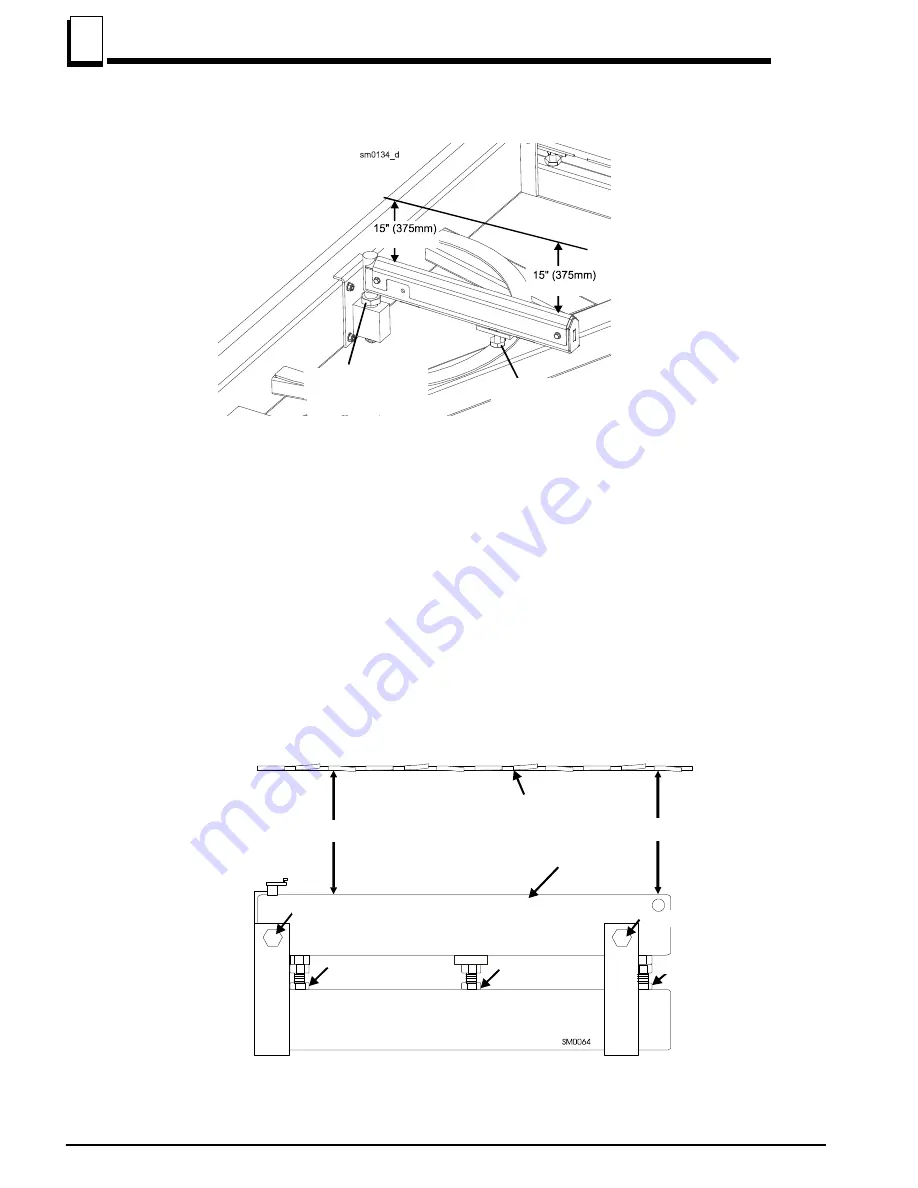
See Figure 5-13.
Optional bed rail (angled)
6.
Loosen the jam nut and turn the outer height adjustment bolt to adjust the height of the outer end of
the pivot rail.
7.
Move the cutting head so the blade is positioned over the center of the front main bed rail.
8.
Measure the distance between the bottom of the blade and the bed rail at each end of the bed rail.
The bed rail should measure 15" (375 mm) (+ 1.0 mm on the outer end) from the blade at each end
of the rail.
See Figure 5-14.
FIG. 5-13
FIG. 5-14
Outer Height
Adjustment Bolt
to blade
to blade
Inner Height
Adjustment Nut
375,0 mm + 1,0 mm
375,0 mm
Blade
Bed rails
Clamp bolt
Clamp bolt
Adjustment bolt
Adjustment bolt
Adjustment bolt
a
Blade
Bed rails
Clamp bolt
Clamp bolt
Adjustment bolt
Adjustment bolt
Adjustment bolt
Содержание A/DH5
Страница 1: ...Table of Contents Section Page Table of Contents SW 07doc1115171...
Страница 2: ......
Страница 41: ...SETUP OPERATION Sawmills with cable guide SETUP OPERATION doc111517 2 7 2 FIG 2 4 LT40MRC K 7 B5 1 B0 18...
Страница 86: ...1 18 30doc111517...


