www.wobit.com.pl
User manual -ADT42 – 23.06.2015 – v.1.3
page 10
2)
Introducing value 500
(3)
in „Rated capacity” window for sensors 1 and 2
3)
Introducing value 1,5 (
3
) in „Rated output” window for sensors 1 and 2
4)
Zeroing of sensor’s offset –
button for each channel independently or
for all channel
simultaneously(
3
)
5)
Saving of settings to device –„
Save
” button (
6
)
For multivariant measurements we recommend to set filtration on „
Slow
” and select filtration level
to achieve compromise between measurement stability and response time on change of force. (
2
).
Each value change should be saved by „
Save
” button (6)
3.3
Configuration of output and RS485
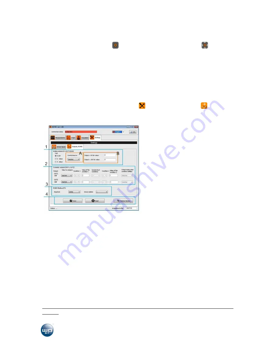
After starting ADT42-PC application go to
Settings
tab, then to
Outputs, RS485
tab.
1)
Setting of analog output. A – selection of signal
source, sent on 0-10V/4-20mA output, B –
calibration of analog output
2)
Setting of transistor outputs OUT 1 and OUT2.
3)
Setting of communication parameters RS485
MODBUS
4)
Reading and saving set parameters to module
and factory settings recall
3.3.1
Configuration of analog output
This options allows to determine:
Output type: 0-10V, 0-20mA or 4-20mA
Controlling value (
A
), which will be transferred to analog output. As controlling value you
can select one of 4 channels or aggregate of active channels.
Calibration of input value (
B
) in relation to controlling signal.
Depend on module version it will be allowable proper analog output:
ADT42-U
– module with voltage output – allowable selection 0-10V
ADT42-I
– module with current output – allowable selection 0-10mA or 4-20mA
Example 1
: For aggregate value in range of 0-2000 analog output can change in range from 4mA up
to 20mA
1)
Setting of output mode for
4-20mA


