background image

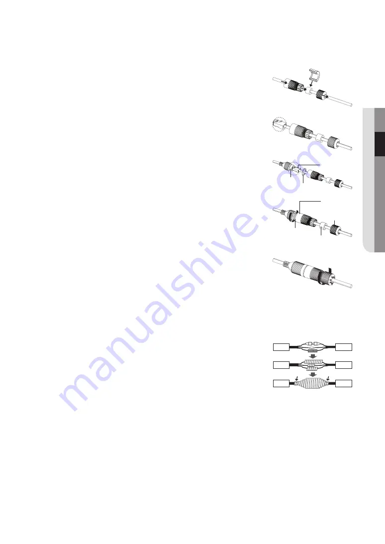
how to connect the rJ45 waterproof cable to a lan cable

1. 

Insert it through the arrow direction.

2. 

Connect the LAN connector (male) to the cable.

3. 

Connect the RJ45 modular jack (female) to the RJ45 connector (male).


J


`

Please, keep each of the parts separated.

4. 

Assemble by rotating the RJ45 modular jack (female) and the RJ45 protection cover 

clockwise (Follow the arrow).

5. 

Assemble by rotating RJ45 protection cover and back cover clockwise (Follow the 

arrow). 

When the back cover is assembled, the cable waterproof gasket is tightly attached to 

the cable to make it waterproof.


J


`

You must fully assemble it to rotate the back cover up to the end of the screw thread of the RJ45 connector.

outdoor installation

When you install the camera outdoors, it should be waterproofed with waterproof butyl rubber tape (which can be purchased in 

stores) so that water does not leak from the gap of the cable connected in the outdoor area.

1. 

Connect the power and LAN cables.

2. 

Wrap the black cable jacket (Area A) and the cable connection area with waterproof 

(butyl rubber) tape so that more than half of the butyl rubber tape is overlapped.


J


`

If the cable jacket is not waterproofed properly, then it can directly cause leakage. Make sure 

to protect the cable with a dense layer of taping.


`

Waterproof butyl tape is made of butyl rubber that can be stretched to twice its normal length.

English


_9

●  

inst
alla

tion & 

Conne

Ction

RJ45 connector 

(male)

RJ45 modular 

jack (female) Rubber ring


RJ45 connector 

protection cover

Back cover

Cable waterproof 

gasket

Rubber ring

Camera

Camera

Camera

System

System

System

A

A

Содержание ZNE-8020RV

Страница 1: ...ZNE 8020RV ZNO 8020RV NETWORK CAMERA User Manual...

Страница 2: ...V installation connection 8 8 Precautions 8 Installing The Camera ZNE 8020RV 10 Installing The Camera ZNO 8020RV 11 Connect NVR network connection and setup 12 12 Device Connection 13 Device Operation...

Страница 3: ...apparatus When a cart is used use caution when moving the cart apparatus combination to avoid injury from tip over 13 Unplug this apparatus during lighting storms or when unused for long periods of ti...

Страница 4: ...ption Camera 1 Instruction book Installer S W CD 1 Quick Guide 1 Template 1 Product installation guide Tapping Screw 3 Used for installation on the wall or ceiling Plastic Anchor 3 For fixing a screw...

Страница 5: ...Item Name Quantity Description Camera 1 Instruction book Installer S W CD 1 Quick Guide 1 Tapping Screw 3 Used for installation on the wall or ceiling Plastic Anchor 3 For fixing a screw Inserted in a...

Страница 6: ...A cover placed over to fix its position after the head direction has been adjusted c Bottom case This is used to install a camera on the ceiling d Power Cable Connect with the power supply DC12V e Ne...

Страница 7: ...bles you to monitor at a wider field of view b Illumination Sensor Detects incoming light to control the IR LED c Power Cable Connect with the power supply DC12V d Network Port Used to connect the PoE...

Страница 8: ...2 Rotate and release the Fixing cover 3 Using the template provided as an accessory drill holes for installation 4 Align the installation holes of the camera and use the tapping screws to fix the bott...

Страница 9: ...installation When you install the camera outdoors it should be waterproofed with waterproof butyl rubber tape which can be purchased in stores so that water does not leak from the gap of the cable con...

Страница 10: ...the cable connectors may be wet with moisture or pile up with impurities Although the camera is IP66 rated direct exposure to water or moisture may cause problem such as condensation 4 Attach the came...

Страница 11: ...cket Area A and the cable connection area with waterproof butyl rubber tape so that more than half of the butyl rubber tape is overlapped J J If the cable jacket is not waterproofed properly then it c...

Страница 12: ...C within one minute after being powered on if the network operates normally Connection to router switch This is more commonly used in connecting the IP camera to Internet where the camera and PC are c...

Страница 13: ...normally and the network is connected properly 3 If the PING command fails check IP address and gateway setting of the PC and connectivity of the network Searching Device J J Device Search may be use...

Страница 14: ...n Upgrade it can offer 1pcs or more than 1pcs IP camera upgrade Please choose the IP camera you want to upgrade in the left frame Open the icon to choose the software you want put in the user name and...

Страница 15: ...ppears enter the new password J J For a new password with 8 to 9 digits you must use at least 3 of the following For a new password with 10 to 13 digits you must use at least 3 of the following Combin...

Страница 16: ...tch Video preview switch enable disable h original preview frame ratio View mode in which the video is played in the actual resolution i automatic preview frame ratio A view mode in which the size of...

Страница 17: ...llowing dialog box 2 In this dialog box you can set video storage location paths for download of remote file and storage of image snapshot file type RF by default in H 265 encoding capture type BMP by...

Страница 18: ...l Go to Remote Setting Image Control to enter into the interface IR CUT Mode Select the desired built in IR cut filter mode to ensure the camera works properly both in the day and night IR CUT Delay S...

Страница 19: ...rivacy Zone Privacy Zone is to block certain area s in the camera s field of view on live video 1 Check Enable Privacy zone 2 Press down and hold the left mouse button and drag out a area for privacy...

Страница 20: ...econd the camera will record Video Code Type Select a type of profile Video Code Level Bitrate Control Select either constant CBR variable VBR bitrate Bitrate Mode Select default custom bitrate Bitrat...

Страница 21: ...e multiple cameras in a LAN make sure their MAC addresses are different DDNS Go to Remote Setting Network DDNS to enter into the menu interface User may set DDNS in any one of the above 3 network conn...

Страница 22: ...istered account 2 From the top menu bar select MY DDNS 3 Click the Register Product tab 4 Select DDNS button 5 Enter the product ID 6 Select a Type and specify the Model 7 Specify the product location...

Страница 23: ...r the password of the SMTP server user Sender Sender s mail address which must correspond to the server used For example mailbox aaa gmail com should correspond to server smtp gmail com Receiver 1 2 3...

Страница 24: ...ter Go to Remote Setting Network IP Filter to enter the interface You can create a list of IPs that you want to grant or deny access to them 1 Select filtering mode Allow all IP connections If selecti...

Страница 25: ...users including one administrator and six users Click number to enter into the user edit interface to input user name and password User Name consists of 8 characters Password MUST be 8 13 characters...

Страница 26: ...Device System of wireless camera to ex factory default Firmware Update Go to Remote Setting System Maintenance Firmware Update to enter into the interface Click Scan to enter the Device interface and...

Страница 27: ...y week month When Auto Reboot is enabled camera should be in the main interface and no user operation M M The auto maintain function can be effective only when camera returns back to Preview mode with...

Страница 28: ...to a Broadband Router verify that port forwarding is properly configured Viewer got disconnected during monitoring Connected Viewers become disconnected upon any change to camera or network configurat...

Страница 29: ...ectangle Gain Control Off Low Middle High White Balance ATW Manual Electronic Shutter Speed Auto Manual Flip Mirror Flip 0 180 Mirror Network Ethernet RJ 45 10 100BASE T Video Compression Format H 264...

Страница 30: ...zilla Firefox Ver 51 x or lower Google Chrome Ver 44 x or lower Safari 11 1 1 or lower Environmental Operating Temperature Humidity 10 C 55 C 14 F 131 F Less than 90 RH Ingress Protection IP66 Electri...

Страница 31: ...Dimension ZNE 8020RV Unit mm inch 90 3 54 75 2 95 100 3 94 100 3 94 60 2 36 English _31 Appendix...

Страница 32: ...ZNO 8020RV Unit mm inch 68 2 68 7 1 2 2 8 3 4 3 0 17 64 8 2 55 114 3 4 5 Appendix 32_ Appendix...

Страница 33: ...onic accessories should not be mixed with other commercial wastes for disposal Correct disposal of batteries in this product Applicable in the European Union and other European countries with separate...

Страница 34: ...nd Western Express Highway Goregaon E Mumbai 400 063 India Phone 91 22 67114444 www compuageindia com Compuage Infocom LTD Service Center Address Geetha Industrial Estate Gala No 8 9 10 11 First Floor...

Отзывы: