


30
31
English
English
In the case of larger deviations, please consult the manufacturer.
Please consult the appropriate operating manual for details on
inspecting the safety and monitoring devices on the auxiliary
lifting gear.
Changing the lubricant
The drained lubricant must be checked for dirt and water
content. If the lubricant is very dirty and contains more than
1/3 water, it must be changed again after four weeks. If there
is again water in the lubricant then, it seems likely that a seal
is defective. In this case, please consult the manufacturer. If a
sealing room or leakage monitoring system is being used, the
display will light up again within four weeks of changing the
lubricant if a seal is defective.
7.5 Repairs
When carrying out repair work, the following information
should always be noted:
- Round sealing rings as well as existing seals should always
be replaced.
- Screw fixings such as spring washers or the self-locking
Nord-Lock screw fixing should always be replaced.
- If no self-locking Nord-Lock screw fixing is used as a locking
screw or it is not possible to use these, then no dacromet-
coated screw should be used. In this case, screws made from
the material A2 or A4 must be used. The correct torques
must be observed.
- Never use brute force during this work.
Changing sealing parts
Changing sealing parts on the liquid side such as the block seal
cartridge and the mechanical seal shaft requires a certain amount
of specialist knowledge about these sensitive components.
In addition to this, in order to carry out the work, much of the
machine must be dismantled.
8 Shutdown
8.1 Temporary shutdown
For this type of shutdown, the machine remains installed
and is not cut off from the electricity supply. For temporary
shutdown, the machine must remain completely submerged so
that it is protected from frost and ice. Make sure the operating
room and the pumped fluid cannot be covered by ice. This
ensures that the machine is always ready for operation. During
longer shutdown periods, carry out a regular (monthly to
quarterly) function run for a period of 5 minutes.
8.2 Final shutdown / storage
Beware of hot parts!
When removing the machine, be careful of the
temperature of the housing components. These can
heat up to well above 40° C. Let the machine cool down
to ambient temperature before you touch it.
Switch off the system, disconnect the machine from the electricity
supply and dismantle and store it. Note the following information
concerning storage:
- Clean the machine.
- Store it in a clean, dry place, protect the machine against
frost.
- Place it down vertically onto a firm foundation and secure it
against falling.
- Seal the intake and discharge ports of pumps with suitable
material (such as foil).
- Support the electric connecting lead on the cable lead-in to
help avoid a permanent deformation.
- Protect the ends of the electric power cable from moisture.
- Protect the machine from direct sunshine as a preventive
measure against brittleness in elastomer parts and the
propeller and casing coating.
- When storing the machine in a garage please remember:
Radiation and gases which occur during electric welding
destroy the elastomers of the seals.
- During lengthy periods of storage, regularly (for example
every six months) turn the impeller or propeller by hand.
This prevents indentations in the bearings and stops the
rotor from rusting up.
8.3 Restarting after an extended period of storage
Before restarting the machine, clean it of dust and oil deposits.
Then carry out the necessary mainte-nance actions (see
“Maintenance”). Check that the mechanical shaft seal is in
good order and working properly.
Once this work has been completed, the machine can be
installed (see “Installation”) and connected to the electricity
supply by a specialist. See “Startup” a for instructions on
restarting.
Only restart the machine if it is in perfect condition and ready
for operation
9 Troubleshooting
In order to prevent damage or serious injury while rectifying
machine faults, the following points must be observed:
- Only attempt to rectify a fault if you have qualified staff. This
means each job must be carried out by trained specialist
staff, for example electrical work must be performed by a
trained electrician.
- Always secure the machine against an accidental restart by
disconnecting it from the electric system. Take appropriate
safety precautions.
- Always have a second person make sure the machine is
switched off in an emergency.
- Secure moving parts to prevent injury.
- Independent work on the machine is at one's own risk and
releases the manufacturer from any warranty obligation.
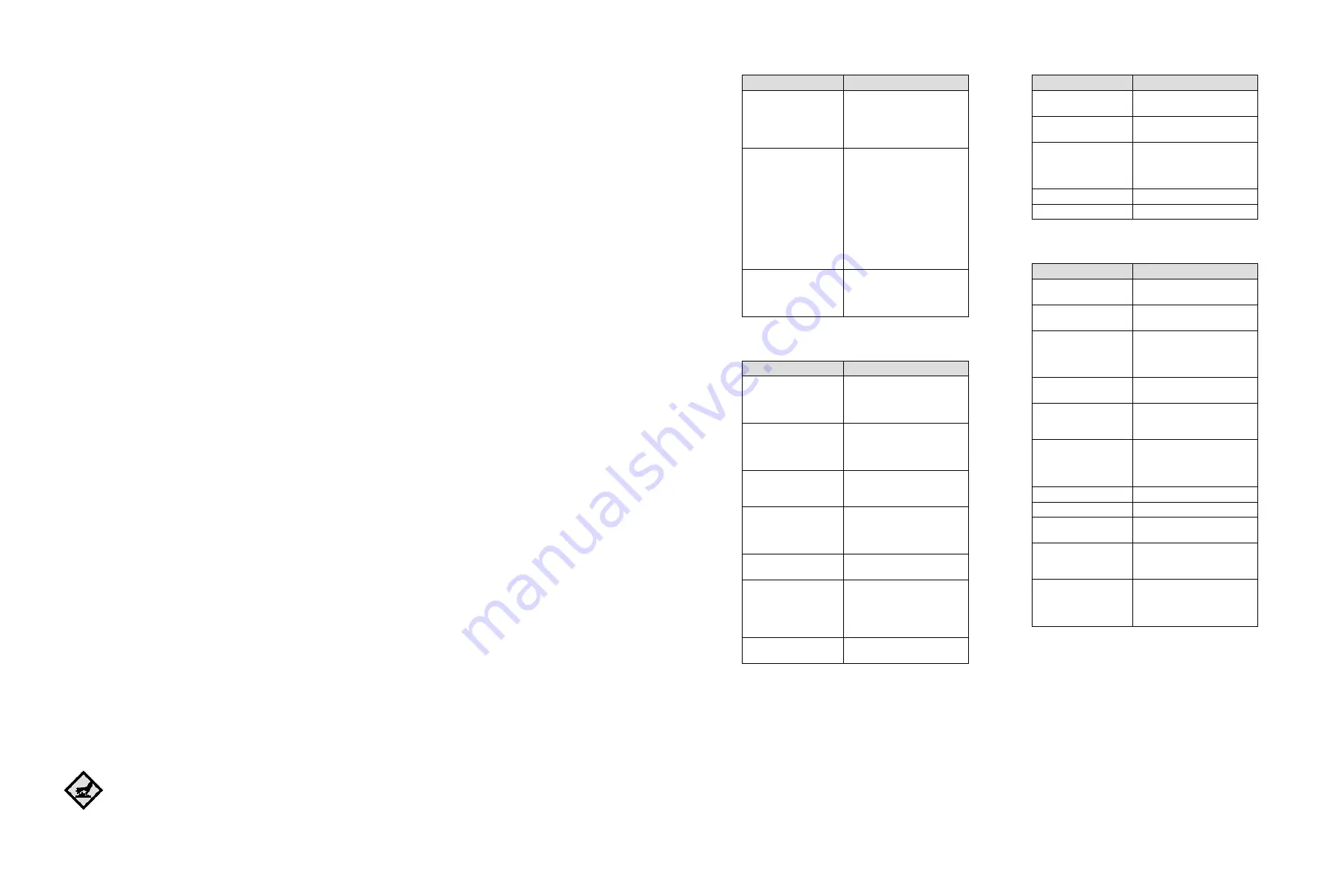
Fault1: The machine will not start
Cause
Remedy
Electricity supply
interrupted – short circuit
or
earth connection in the
cable or motor windings
Have the motor and wires
checked by a specialist and
replaced if necessary
Fuses, the motor
protection switch and/
or monitoring devices are
triggered
Have a specialist inspect the
connection and correct them as
necessary
Have the motor protection
switch adjusted
according to the technical
specifications, and reset
monitoring equipment
Check that the impeller/
propeller runs smoothly. Clean it
or free it as necessary
The moisture sensors
(option) has interrupted
the power circuit
(operator-related)
See fault: Mechanical shaft seal
leaks, sealing chamber monitor
reports fault and switches
the machine off
Fault2: The motor starts, but the motor protection switch
triggers shortly after start-up
Cause
Remedy
The thermal trigger on
the motor protection
switch is incorrectly set
Have a specialist compare the
setting of the trigger with the
technical specifications and
adjust it if necessary
Increased power
consumption due to
major voltage drop
Have an electrician check the
voltage on each
phase and rewire if necessary
Two-phase operation
Have a specialist inspect the
connection and correct it as
necessary
Excessive voltage
differences on the three
phases
Have a specialist inspect the
connection and the switching
system and correct it as
necessary
Incorrect direction of
rotation
Swap the 2 phases from the
mains supply
Impeller/propeller
impeded by adhesive
material, blockages and/
or solid matter, increased
current consumption
Switch off the machine, secure
it against being switched on
again and free the impeller/
propeller or clean the suction
port
The pumped fluid is too
dense
Contact the manufacturer
Fault3: Machine runs but does not pump
Cause
Remedy
No pumped fluid
Open the container intake or
sliders
Intake blocked
Clean the intake, slider, suction
port or intake strainer
Impeller/propeller blocked
or obstructed
Switch off the machine, secure
it against being switched on
again and free the impeller/
propeller
Defective hose or piping Replace defective parts
Intermittent operation
Check the control panel
Fault4: The machine runs, but not at the stated operating
levels
Cause
Remedy
Intake blocked
Clean the intake, slider, suction
port or intake strainer
Slide in the discharge line
closed
Fully open the slide
Impeller/propeller blocked
or obstructed
Switch off the machine, secure
it against being switched on
again and free the impeller/
propeller
Incorrect direction of
rotation
Replace 2 phases on the mains
supply
Air in the system
Check the pipes, pressure
shroud and/or pump unit, and
bleed if necessary
Machine pumping against
excessive pressure
Check the slide in the discharge
line, if necessary open it
completely, use a different
impeller or contact the factory
Signs of wear
Replace worn parts
Defective hose or piping Replace defective parts
Inadmissible levels of gas
in the pumped liquid
Contact the factory
Two-phase operation
Have a specialist inspect the
connection and correct it as
necessary
Excessive decrease in the
water table during operation
Check the supply and capacity
of the system, and inspect
the level control settings and
function


