


64
3)
Coolant flow sensor
Regularly check and maintenance coolant flow sensor,clear up the impurities
accumulated inside coolant flow sensor,otherwise it affect the actual value of coolant
flow,causing false alarm.
4)
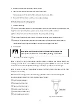
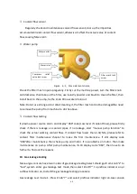
Water pump
Figure 6-2 Pump elements name
Check the filter mesh in pump regularly. Firstly cut the machine power, turn the filter knob
anticlockwise, then take out the filter, use laundry powder and brush to clean the filter, then
install back to the pump, fix the knob till no water drain out.
Note:Do not use strong acid or alkali cleaning it, the filter mesh cannot be damaged.No need
to remove the pump from machine to do the above.
5)
Coolant flow testing
If plasma power source alarm and display “060”code (Low level if coolant flow), please firstly
check if there is leakage on coolant pipes, if no leakage, start “manual pump function” to
check the actual working coolant flow. If coolant flow lower than 2.3L/Min, please refer to
coolant filter maintenance chapter to make the first maintenance. If still display code
“060”after maintenance, then check pump and motor. If no problems on motor, than make
maintenance on pump. After pump maintenance, if still display code “060”, then have to do
further to find out the reasons.
10. Gas leakage testing
Manual gas console have two modes of gas leakage testing.Select shield gas from knob“2” to
“test”,system enter gas leakage test mode,then select knob“7” to preflow indicator on,or
cutflow indicator on,to start the gas leakage testing procedure.
Gas leakage test mode 1: Press Knob“7” and select preflow indicator light on.Gas console
Filter mesh lock
screw
Water outlet
Water inlet
Compress
relief
valve lock screw
Содержание FLG-200HD
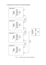
Страница 9: ...5 Figure 2 1 System connection diagram ...
Страница 43: ...39 Figure 5 2 SQK A1 front panel function Figure 5 3 SQK B1 front panel function ...
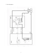
Страница 74: ...70 4 System wiring diagram Figure 7 1 System wiring diagram ...
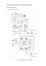
Страница 77: ...73 2 Main circuit wiring diagram 2 Figure 7 4 FLG 200HD Main circuit wiring diagram 2 ...
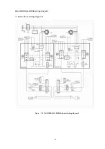
Страница 79: ...75 4 Main circuit wiring diagram 2 Figure 7 6 FLG 300HD FLG 400HD Main circuit wiring diagram 2 ...
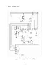
Страница 80: ...76 5 Main circuit wiring diagram 3 Figure 7 7 FLG 300HD FLG 400HD Main circuit wiring diagram 3 ...
Страница 81: ...77 6 HF striking diagram Figure 7 8 HF striking diagram ...


