43
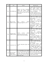
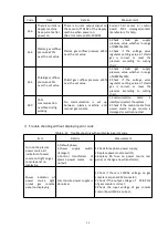
300s,Knob 8 run to “AMPS”automatically, the digital tube displays the set current,the
corresponding ERROR type indicator under Knob 8 will off.
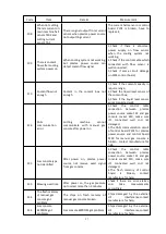
② Low priority error
When low priority error appear, the complete machine changes the work process and enter
stand by status, there will be no any display changes on panel, press knob 8 and select
“ERROR”, we can see the error code display on the digital tube.
③ High priority error
When high priority error appear, the complete machine changes the work process and enter
stop status, user can only restart the machine. Knob 8 will automatically run to“ERROR”and
error indicator flicker (light on 0.3s and light off 0.3s). Error code will be displayed on the
digital tube, the corresponding ERROR type indicator under Knob 8 will flicker(light on 0.3s
and light off 0.3s).
4. How to optimize cutting quality
Following points and steps help to get more vertical, smooth and slag-free cutting kerf,to
improve cutting quality.
1)
Matters need attention when use cutting table and plasma torch
① Use I-square check the vertical of the torch and work-piece, make sure it’s vertical.
② Clean and check the rail and transmit device on cutting table, test it to get more smooth
torch moving. Unstable moving causes cutting roughness.
③ When cutting, plasma torch can not contact with work-piece, or it damages the shield
cap and nozzle, cause bad cutting surface.
2)
Gas pressure setting
Operate it as the steps in the chapter “inspection before start”process.
Blow the gas pipelines before cutting.
3)
Lengthen the wearing parts working life
① Don’t strike arc without contacting work-piece
Can strike arc on edge of work-piece, but don’t strike without contacting work-piece.
If piercing at the beginning, please set piercing height 1.5-2 times distance (between torch to
work-piece)than normal cutting.
② Make sure the cutting arc still on the work-piece after every cutting finish, to avoid arc
extinguish.
Содержание FLG-200HD
Страница 9: ...5 Figure 2 1 System connection diagram ...
Страница 43: ...39 Figure 5 2 SQK A1 front panel function Figure 5 3 SQK B1 front panel function ...
Страница 74: ...70 4 System wiring diagram Figure 7 1 System wiring diagram ...
Страница 77: ...73 2 Main circuit wiring diagram 2 Figure 7 4 FLG 200HD Main circuit wiring diagram 2 ...
Страница 79: ...75 4 Main circuit wiring diagram 2 Figure 7 6 FLG 300HD FLG 400HD Main circuit wiring diagram 2 ...
Страница 80: ...76 5 Main circuit wiring diagram 3 Figure 7 7 FLG 300HD FLG 400HD Main circuit wiring diagram 3 ...
Страница 81: ...77 6 HF striking diagram Figure 7 8 HF striking diagram ...


