67
WHL-012 REV. 12.17.14
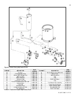
Figure 53
– Combustion System Replacement Parts
NUMBER
DESCRIPTION
PART
NUMBER
NUMBER
DESCRIPTION
PART
NUMBER
24
Air Intake Pipe
7855P-071
28
Gas Outlet Pipe
7855P-233
25-A
Gas Orifice Nozzle (NG) 6.5mm
7855P-228
29
Gas Valve
7855P-034
25-B
Gas Orifice Nozzle (LP) 5.4mm
7855P-229
30
Gas Valve Bracket
7855P-234
26
Burner Assembly
7855P-230
31
Gas Valve Inlet Adapter
7855P-033
26-1
Burner Inlet Channel
7855P-231
32
Gas Inlet Pipe
7855P-235
26-2
Air Gas Mixer
7855P-027
33
Heat Exchanger Assembly
7855P-236
26-3
Fan
7855P-025
34
Condensate Collector Pan
7855P-061
26-4
Burner Overheat Sensor
7855P-066
35
Flame Sensor
7855P-031
26-5
Ignition Rod
7855P-068
36
Exhaust Pipe
7855P-237
26-6
Burner Body
7855P-067
37
CH Supply Temperature Sensor
7855P-030
26-7
Ceramic Fiber Burner
7855P-069
38
Water Level Detection Sensor
(Low Water Cut Off)
7855P-029
27
Gas Valve Outlet Adapter
7855P-232
Table 29
– Combustion System Replacement Parts
Содержание WBRCLP140F
Страница 2: ...2 WHL 012 REV 12 17 14 ...
Страница 38: ...38 WHL 012 REV 12 17 14 Figure 26 Electrical Wiring Diagram ...
Страница 39: ...39 WHL 012 REV 12 17 14 Figure 27 Ladder Diagram ...
Страница 73: ...73 WHL 012 REV 12 17 14 ...
Страница 74: ...74 WHL 012 REV 12 17 14 ...
Страница 75: ...75 WHL 012 REV 12 17 14 MAINTENANCE NOTES ...


