56
WHL-012 REV. 12.17.14
G. CONDENSATE REMOVAL
1. This is a high efficiency condensing appliance. Therefore, the appliance has a condensate drain. Condensate fluid is nothing more
than water derived from combustion products, similar to that produced by an automobile when it is initially started.
Condensate is slightly acidic (typically with a pH of 3 to 5) and must be piped with the correct materials. Never pipe the condensate
using steel, copper, brass or other materials that will be subject to corrosion. Plastic PVC or CPVC pipe are the only approved
materials.
A condensate neutralizer, if required by local authorities, may be purchased from Westinghouse (7450P-212).
2. The appliance is
provided with a ½” X ¾” reducing coupling that must be installed on the appliance before the condensate is piped to
a local drain. It is very important that the
minimum ¾” condensate line is sloped downward away from the appliance to a suitable inside
drain. If the condensate outlet on the appliance is lower than the drain, you must use a condensate removal pump, available from
Westinghouse (554200). This pump is equipped with two leads that
can be connected to an alarm or another type of warning device to
alert the user of a condensate overflow, which, if not corrected, could
cause property damage.
3. If a long horizontal run is used, it may be necessary to create a vent
in the horizontal run to prevent a vacuum lock in the condensate line.
4. Do not expose the condensate to freezing temperatures.
5. It is very important you support the condensate line to assure
proper drainage.
H. FINAL CHECKS BEFORE STARTING APPLIANCE
1. Verify the appliance and system are full of water and all system
components are correctly set for operation.
2. Fill the condensate trap with water.
3. Verify electrical connections are correct and securely attached.
4. Inspect exhaust vent and intake piping for signs of deterioration
from corrosion, physical damage, or sagging. Verify exhaust vent and
intake piping are intact and correctly installed per Venting Section (this
manual) and local codes.
I. ADJUSTING GAS PRESSURE AT THE APPLIANCE
NOTE:
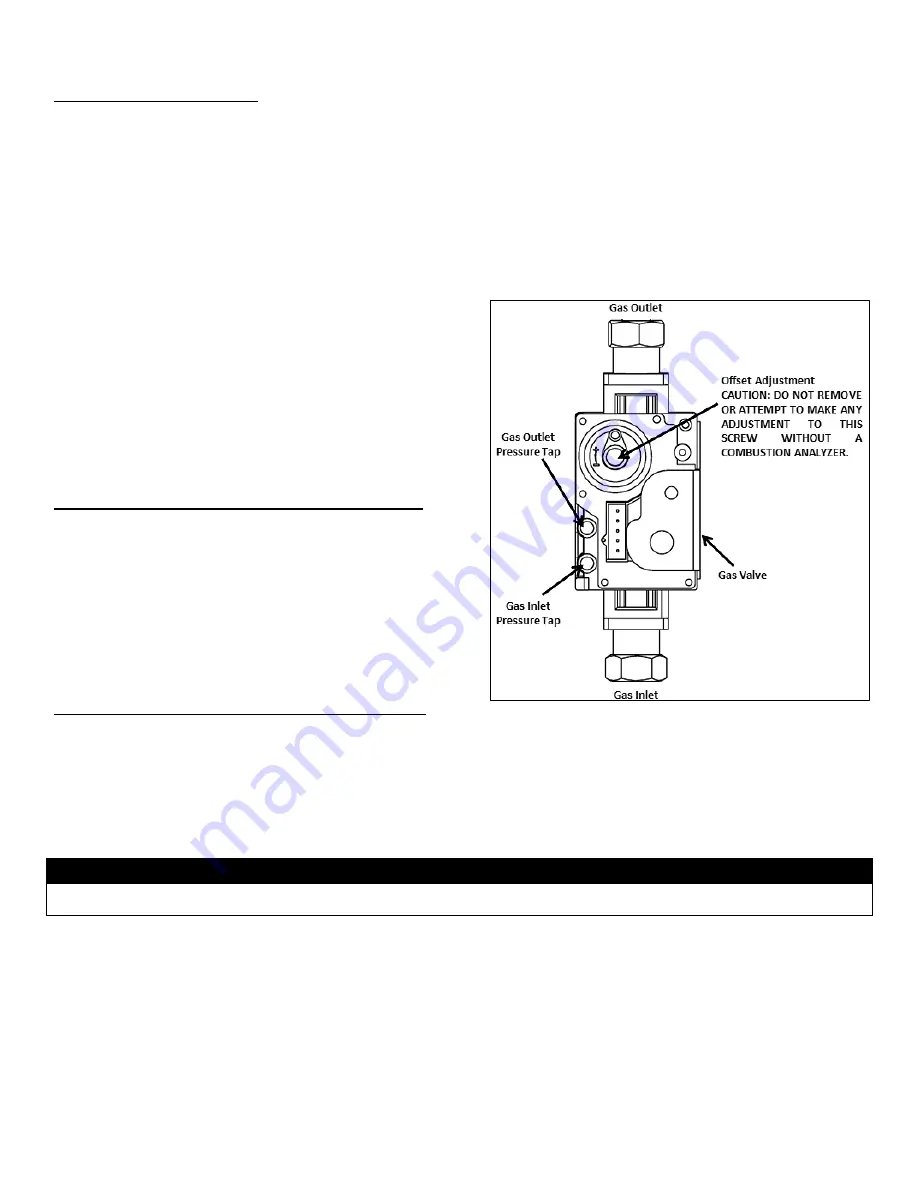
Refer to Figure 43 when adjusting gas pressure. Loosen the
screw before checking the gas inlet pressure.
1. The appliance and its individual shutoff valve must be disconnected from the gas supply piping system during any pressure testing of
the system at test pressures greater than ½ psi (3.5 kPa).
2. The appliance must be isolated from the gas supply piping system by closing its individual manual shutoff valve during any pressure
testing of the gas supply piping system at test pressures equal to or less than ½ psi (3.5 kPa).
NOTICE
Do not fire (operate) the appliance until all connections have been completed and the heat exchanger is filled with water. Doing so will
damage the appliance and void the warranty.
ADJUSTING GAS PRESSURE AT THE APPLIANCE
1. Open the gas line and water valves.
2. Use a Phillips Head screwdriver to remove the appliance top cover. Remove the front cover.
3. Loosen the gas inlet pressure tap screw three turns with a screwdriver. Connect the manometer to the inlet gas pressure port. See
Figure 43.
4. Turn on power to the appliance and open a hot water faucet.
5. The minimum and maximum inlet gas line pressures must meet the requirements shown in Table 23.
Figure 43
–Gas Valve Detail
Содержание WBRCLP140F
Страница 2: ...2 WHL 012 REV 12 17 14 ...
Страница 38: ...38 WHL 012 REV 12 17 14 Figure 26 Electrical Wiring Diagram ...
Страница 39: ...39 WHL 012 REV 12 17 14 Figure 27 Ladder Diagram ...
Страница 73: ...73 WHL 012 REV 12 17 14 ...
Страница 74: ...74 WHL 012 REV 12 17 14 ...
Страница 75: ...75 WHL 012 REV 12 17 14 MAINTENANCE NOTES ...


