Westinghouse WBCETNG1000 Скачать руководство пользователя страница 44

WHL-038 Rev. 1.29.16

44

3.  Next,  check  the  boiler  settings.  Adjustment  and  factory 
defaults are outlined within this section. If a cascade system is 
used,  it  is  important  that  all  the  boilers  have  the  same  boiler 
settings. 
4.  Next,  check  the  system  settings.  Adjustments  and  factory 
defaults are outlined within this section. If a cascade system is 
used, it is important that the Master Boiler is programmed with 
the correct system settings.
5. Create a demand on the boiler or boilers if a cascade system 
is used. The user can monitor system functions when the boilers 
are operational. 
6. If the boilers fail to start, refer to the troubleshooting section 
in the back of this manual.

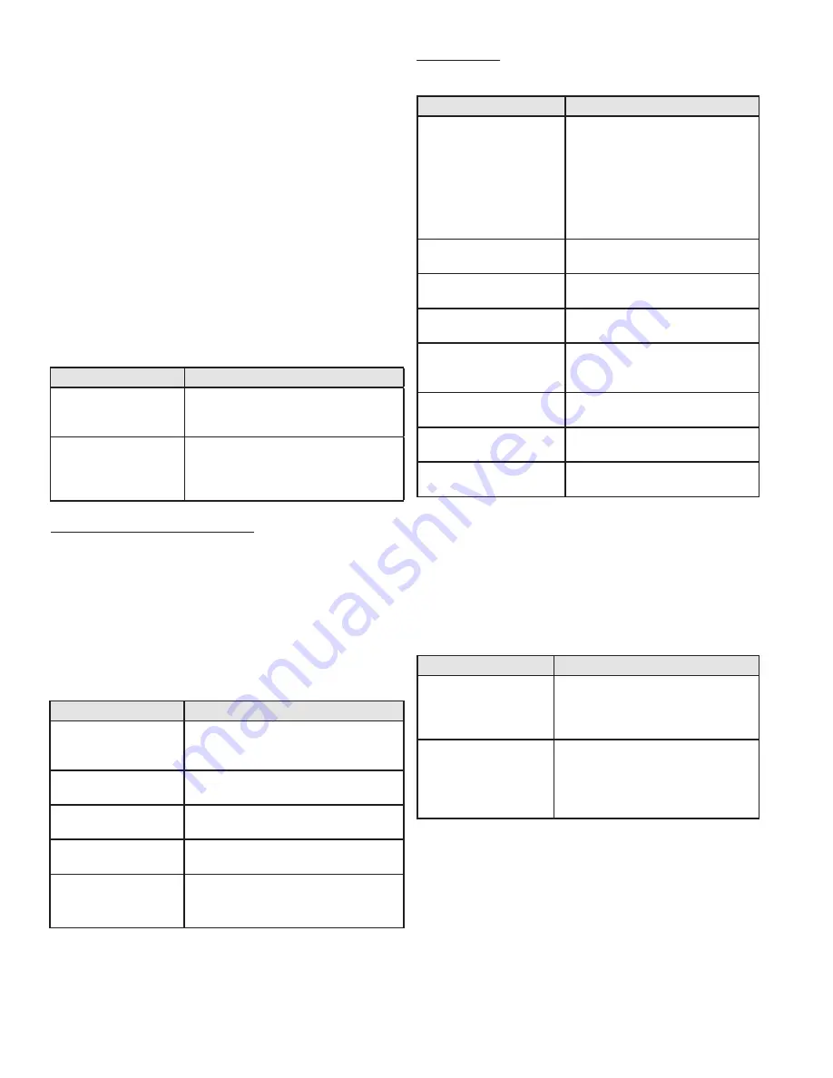
D. Programming Boiler Settings

Boiler Setting Program Access 

Note: Programming the boiler control is not possible when the 
boiler is firing. Make sure any input which can create a demand 
on the boiler, such as the tank thermostat, is turned off, so the 
boiler will remain idle to allow programming. 

Screen

Description

ENTER   MENU   CODE
000

To  access  the  boiler  setting  program, 
press and hold 

ENTER

 for 4 seconds until 

the display shows the screen at left.

ENTER   MENU   CODE
600

Use  the  arrow  keys  to  log  in  the 

Boiler 

Menu Access Code - 600

.  Press 

ENTER


to confirm the code and access the 

Boiler 

Setting Program

 navigation menu.

Table 12 - Boiler Setting Access

Boiler Setting Program Navigation

Once the code is confirmed, the user can start to set the 

Boiler 

Settings

. Use the arrow keys on the display to navigate through 

the 

Boiler Settings

. A blinking setting indicates the setting can 

be changed. To change a setting, press 

ENTER

. Boiler settings 

can be increased by pressing 

and decreased by pressing 

v

 on 

the  display.  When  done,  press 

ENTER

.  The  setting  will  stop 

blinking and the user can move on to next setting by pressing 

the 

or

 > 

arrow keys. Press 

RESET

 to exit programming and 

store settings. Listed below are the boiler settings that can be 
programmed into the control.

Screen

Description

CENTRAL   HEAT
180 

o

F

Allows  the  user  to  adjust  the  boiler    set 
point from 50F to 190

o

F (Factory Default 

180

o

F).

CENTRAL   DIFF   SET
 30 

o

F

Adjusts  the  boiler  differential  set  point 
from 5

o

F to 30

o

F (Factory Default 30

o

F).

DHW   SETPOINT
119 

o

F

Adjusts  the  indirect  tank  set  point  from 
70

o

F to 185

o

F (Factory Default 119

o

F).

DHW   DIFF   SETPOINT
  7 

o

F

Adjusts  the  DHW  differential  set  point 
from 1

o

F to 30

o

F (Factory Default 7

o

F).

TEMP  DISPLAY  C OR F


o

F

Adjusts 

the 

temperature 

measurement in F = Fahrenheit to C = 
Celsius (Default is Fahrenheit).

Table 15 - Boiler Setting Program Navigation

Clock Settings

(

NOTE:

 The clock will reset if the boiler is powered off for 

more than a week.)

Screen

Description

CLOCK   MODE       (12/24)
08/28/2009            Fr  9:42A

Changes  the  clock  from  12  hour 
mode  (8:45  PM)  to  24  hour  mode 
(20:45). To change to 24 hour mode, 
press 

ENTER

.  The  letter  (A  or  P) 

after  the  time  will  blink.  Press  the 
up or down arrow key once and the 
letter will disappear. Press 

ENTER

 to 

save the new setting.

CLOCK   HOUR       
08/28/2009            Fr 10:01A

Allows  the  user  to  adjust  the  hour 
setting.

CLOCK   MINUTE       
08/28/2009            Fr 10:01A

Adjusts the minute setting.

CLOCK   DAY   OF   WEEK       
08/28/2009            Fr 10:01A

Adjusts the day of the week.

CLOCK   DATE   MODE       
08/28/2009            Fr 10:01A

Allows  the  user  to  switch  to 
European  date  format  (2009/08/28) 
from US format (08/28/2009).

CLOCK   YEAR       
08/28/2009            Fr 10:01A

Adjusts the year setting.

CLOCK   MONTH       
08/28/2009            Fr 10:01A

Adjusts the month setting.

CLOCK   DATE       
08/28/2009            Fr 10:01A

The clock is set.

Table 13 - Clock Setting Screens

NOTE:

 The internal clock does not adjust for daylight savings 

time and requires manual adjustment.

E. Programming the System Setting

System Setting Program Access 

Note:  Programming  the  boiler  control  is  not  possible  when 
the  boiler  is  firing.  Make  sure  any  input  which  can  create  a 
demand on the boiler, such as the tank thermostat, is turned 
off, so the boiler will remain idle to allow programming. 

Screen

Description

ENTER   MENU   CODE
000

To  access  the  boiler  setting  program, 
press  and  hold 

ENTER

  for  4  seconds 

until  the  display  shows  the  screen  at 
left.

ENTER   MENU   CODE
925

Use the arrow keys to log in the 

Boiler 

Menu Access Code - 925

. Press 

ENTER


to  confirm  the  code  and  access  the 

System Setting Program

  navigation 

menu.

Table 14 - System Setting Access

F. System Setting Program Navigation

Once the 

System Menu Access Code

 is confirmed, the user 

can begin to set the system setting menu. Use the 

< >

 keys 

on  the  display  to  navigate  through  the  System  Settings. 
To  change  a  setting,  press 

ENTER

. System  settings  can  be 

increased

  by  pressing 

^

 and 

decreased

  by  pressing 

v

 on 

the display. When done, press 

ENTER

. The setting will stop 

blinking and you can move on to next setting. Press 

RESET


to exit programming and store settings. Listed below are the 
boiler settings that can be programmed into the control.

Содержание WBCETNG1000

Страница 1: ...ven order Failure to do so could result in substantial property damage severe personal injury or death Westinghouse reserves the right to make product changes or updates without notice and will not be held liable for typographical errors in literature NOTETO CONSUMER PLEASE KEEP ALL INSTRUCTIONS FOR FUTURE REFERENCE WHL 038 Rev 1 29 16 Improper installation adjustment alteration service or mainten...

Страница 2: ...VICINITY OFTHIS OR ANY OTHER APPLIANCE WHATTO DO IFYOU SMELL GAS Do not try to light any appliance Do not touch any electrical switch Do not use any phone in your building Immediately call your gas supplier from a neighbor s phone Follow the gas supplier s instructions If you cannot reach your gas supplier call the fire department Installation and service must be provided by a qualified installer ...

Страница 3: ...idual such as a fire chief fire marshal chief of a fire prevention bureau labor department or health department building official or electrical inspector or others For the Installer This boiler must be installed by qualified and licensed personnel The installer should be guided by the instructions furnished with the boiler and by local codes and utility company requirements In the absence of local...

Страница 4: ...In addition if the control senses that the outlet water temperature has reached 210 F the boiler is put into a hard lockout and requires manual reset to restart The hydronic supply and return connections of these products are for installation in closed loop systems ONLY Use of this product in any manner other than described in this manual may result in premature product failure substantial propert...

Страница 5: ...t Codes 52 B Boiler Error 52 C Boiler Fault 52 D User Interface Display 53 Part 13 Maintenance 60 A Procedures 60 B Combustion Chamber Cleaning Instructions 60 C CleaningWater Side of Heat Exchanger 61 D Replacing the Door Seal 61 Part 14 Installing the Optional Jacket 64 Part 15 Installation Checklist 65 Part 16 Maintenance Report 65 LimitedWarranty 69 Maintenance Notes 71 Customer Installation R...

Страница 6: ... high efficiency heat exchanger can be damaged by build up or corrosion due to sediment Westinghouse recommends a suction strainer in this type of system Do not use petroleum based cleaning or sealing compounds in boiler system Gaskets and seals in the system may be damaged possibly resulting in substantial property damage Do not use homemade cures or boiler patent medicines Substantial property d...

Страница 7: ...tors boiler return water temperature System Return Temperature and Pressure Gauge Allows the user to monitor system temperature and pressure Electrical field connections with terminal strips The electrical cover allows easy access to the clearly marked line voltage and low voltage terminal strips to facilitate wiring the boiler Supplied Condensate Collection System Field Installed This boiler is a...

Страница 8: ...wo individuals are needed to properly handle the boiler The boiler is also equipped with leveling mechanisms on its casters that can be used to level the boiler properly on an uneven location surface If surface flooring is rough take care when moving the boiler into position as catching the casters could damage the boiler 1 Remove screws on crate sides front and back 2 Remove crate side front and ...

Страница 9: ...s and ordinances when installing this boiler and related components near high heat sources Locate the boiler where any leakage from the relief valve related piping tank or connections will not result in damage to surrounding areas or lower floors of the building The boiler should be located near a floor drain or installed in a drain pan Leakage damages ARE NOT covered by warranty The service life ...

Страница 10: ...e should be 3 4 ID minimum piped to an open drain Failure to follow these instructions could result in property damage Such damages ARE NOT covered by product warranty E Residential Garage Installation Precautions If the boiler is located in a residential garage perANSI Z223 1 Install the boiler burner and ignition devices a mini mum of 18 above the floor of the garage This will ensure the burner ...

Страница 11: ... through the building and properly terminated Different vent terminals can be used to simplify and eliminate multiple penetrations in the building structure see Optional Equipment in Venting Section The exhaust vent and intake piping lengths routing and termination methods must all comply with the methods and limits given in theVenting Section this manual When installing a combustion air intake fr...

Страница 12: ...locations that can allow contamination of intake air Ensurethattheintakeairwillnotcontainanyofthecontaminants inTable 1 Contaminated air will damage the boiler resulting in possible substantial property damage severe personal injury or death For example do not pipe intake air near a swimming pool or laundry facilities These areas always contain contaminants Products to Avoid Areas Likely to Have C...

Страница 13: ...r as water quality will affect the reliability of the system In addition operating temperatures above 140oF will cause the boiler to operate continuously accelerating the build up of lime scale and possibly shortening the service life of the boiler Failure of a boiler due to lime scale build up low pH or other chemical imbalance IS NOT covered by the warranty Sodium less than 20 mGL Water pH betwe...

Страница 14: ...WHL 038 Rev 1 29 16 14 Figure 6 Specifications and Dimensions NOTE All Dimensions Are Approximate ...

Страница 15: ... LEAST ONCE EVERY THREE YEARS and replaced if necessary by a licensed plumbing contractor or qualified service technician to ensure that the product has not been affected by corrosive water conditions and to ensure that the valve and discharge line have not been altered or tampered with illegally Certain naturally occuring conditions may corrode the valve and its components over time rendering the...

Страница 16: ...ser to monitor system pressure and outlet temperature from the boiler It is important to note that the boiler has a minimal amount of pressure drop that must be calculated when sizing the circulators Each boiler installation must have an air elimination device that will remove air from the system Install the boiler so the gas ignition system components are protected from water dripping spraying et...

Страница 17: ...Δt Model Friction Ft Flow Rate GPM Friction Ft Flow Rate GPM Friction Ft Flow Rate GPM 750 2 85 75 1 8 60 1 3 50 1000 1 85 100 1 25 80 0 8 66 6 Table 5 Temperature Rise Friction Ft and Flow Rate In addition the boiler heat exchanger has a minimum total water volume that must be taken into account when sizing the circulator Minimum boiler flow rates are listed in the table below The boiler heat exc...

Страница 18: ...oiler or operate with water containing chlorine in excess of 100 ppm NOTE It is recommended to clean the heat exchanger at least once a year to prevent lime scale buildup To clean the heat exchanger follow the maintenance procedure in this manual H Check Control Water Chemistry Hardness Less than 7 grains Chloride levels Less than 100 ppm pH levels 6 8 TDS Less than 2000 ppm Sodium Less than 20 mG...

Страница 19: ...t be made for this expansion in the system design 4 A 30 mixture of glycol will result in a BTU output loss of 15 with a 5 increase in head against the system circulator Basic steps are listed below that will guide the installation of the boiler 1 Connect the system return marked Inlet 2 Connect the system supply marked Outlet 3 Install purge and balance valve or shut off valve and drain on system...

Страница 20: ...Applications M Zoning with Circulators 1 When using circulator zoning connect the boiler to the system as shown in Applications NOTE The boiler circulator cannot be used for a zone It must only supply the boiler loop 2 Install a separate circulator for each zone 3 Connect DHW domestic hot water piping to indirect storage water heater as shown in Applications N Multiple Boilers 1 Connect multiple b...

Страница 21: ...wn is Primary Secondary 6 The minimum pipe size for connecting a Westinghouse indirect fired water heater is 1 7 The minimum pipe size for connecting a 750 boiler is 2 The minimum pipe size for connecting a 1000 boiler is 2 1 2 8 System flow Secondary Loop must be greater than the boiler s Primary Loop flow 9 Installations must comply with all local codes 10 In Massachusetts a vacuum relief valve ...

Страница 22: ...comply with all local codes 6 Direct piping is shown VERY IMPORTANT Minimum flow rates outlined in the manual must be maintained to minimize short cycling 7 See Multiple Boiler Manifold Piping chart this manual when sizing and installing a multiple boiler system The piping will not support the weight of the circulators Refer to the circulator manufacturer s instructions to properly support the cir...

Страница 23: ...rough an unheated space such as an alcove or attic the space must be heatedorthepipemustbeinsulated Theinsulationmusthave an R value sufficient to prevent freezing of the condensate Improper seating of vent pipe gaskets can cause eventual gasket failure and exhaust gas leakage Ensure the exhaust vent pipe is properly beveled and seated before insertion into the flue adapter Failure to do so could ...

Страница 24: ...8 Approved Materials for ExhaustVent and Intake Pipe C Additional Requirements for Installation in Canada 1 Installations must be made with a vent pipe system certified toULC S636 IPEXisanapprovedventmanufacturerinCanada supplying vent material listed to ULC S636 Additionally you may use AL29 4C stainless steel venting to comply with Canadian requirements 2 The first three 3 feet of vent pipe from...

Страница 25: ...center Minimum distance between exhaust vents and intake pipes on multiple boilers is 10 0 255 m center to center L When adjacent to a public walkway locate exit terminal at least 7 feet above grade In addition Total length of vent piping shall not exceed the limits specified in this manual The vent piping for this direct vented appliance is approved for zero clearance to combustible construction ...

Страница 26: ... PVC and ASTM F493 for CPVC pipe NOTE DO NOT CEMENT POLYPROPYLENE PIPE 4 Ensure the vent is located where it will not be exposed to prevailing winds 5 In all roof venting applications exhaust discharge must point away from the pitch of the roof 6 If the exhaust vent is to be terminated in a walled off area such as a roof with a parapet wall ensure the exhaust vent terminates a minimum of 10 from n...

Страница 27: ...iping could result in property damage serious injury or death Take extra precaution to adequately support the weight of vent pipes terminating through the roof Failure to properly support roof terminated vent piping could result in property damage serious personal injury or death due to flue gas leakage An unbalanced vent system can be installed ONLY when the exhaust is in the vertical position Fa...

Страница 28: ...eded when the boiler is installed in a space with a volume NO LESS than 50 cubic feet per 1 000 BTU hr of all installed gas fired appliances and the building MUST NOT BE of Tight Construction TIGHT CONSTRUCTION A building with less than 4 ACH air changes per hour For buildings of Tight Construction provide air openings into the building from the outside Indoor and outdoor combustion air may be com...

Страница 29: ...ical Room Model Figure 15 Figure 16 Outside Air from 2 Openings Directly from Outdoors1 Outside Air from 2 Ducts Delivered from Outdoors1 Top Opening in2 Bottom Opening in2 Top Opening in2 Bottom Opening in2 750 188 188 375 375 1000 250 250 500 500 Model Figure 17 Figure 18 Inside Air from 2 Ducts Delivered from Interior Space2 Outside Air from 1 Opening Directly from Outdoors in2 1 Same Story Dif...

Страница 30: ... for piping of the condensate neutralizer Figure 19 Condensate Piping NOTES 1 Condensate line must be pitched at least per foot to properly drain If this cannot be done or a very long length of condensate hose is used increase the condensate line to a minimum of 1 ID and place a tee in the line before the condensate neutralizer to properly reduce vacuum lock in the drain line 2 PVC or CPVC pipe sh...

Страница 31: ...tions could result in component or product failure serious injury or death Electrical Shock Hazard Turn off electrical power supply at service entrance panel before making any electrical connections Failure to follow to do so could result in serious injury or death Wiring must be NEC Class 1 If original wiring supplied with the boiler must be replaced use onlyTEW 105 oC wire or equivalent Boiler m...

Страница 32: ...thermostatonaninsidewallascentrallyaspossible totheareabeingheated butawayfromdraftsorheatproducing devices such as television sets that could influence the ability of the thermostat to measure room temperature 3 If the thermostat is equipped with an anticipator and it is connected directly to the boiler the anticipator should be set at 1 amps If the thermostat is connected to other devices the an...

Страница 33: ...side of the gas valve This is normally closed and will open if the pressure goes above 20 w c on the outlet side 2 Locate the two pigtails hanging from the electrical box inside of the boiler cabinet Remove and K Optional Low Gas Pressure Switch 1 If an optional low gas pressure switch is used it should be installed on the inlet side of the gas valve This is normally closed and will open if the pr...

Страница 34: ...2 BOILER NEUT and 3 BOILER GND terminals 2 If you are using an indirect fired water tank connected directly to the follower boiler connect the pump for it to the 4 DHW HOT 5 DHW NEUT and 6 DHW GND terminals If desired an alarm bell or light can be connected to the alarm contacts of the boiler The normally closed alarm contact may be used to turn a device off if the boiler goes into lockout mode Th...

Страница 35: ...WHL 038 Rev 1 29 16 35 Figure 24 CascadeTermination Plug Detail Figure 25 Cascade Master and FollowerWiring ...

Страница 36: ...WHL 038 Rev 1 29 16 36 Figure 26 Internal Connection Diagram ...

Страница 37: ...oved for gas connections Care must be taken when applying compound to prevent blockage or obstruction of gas flow which may affect the operation of the unit Support gas supply piping with hangers not by the boiler or its accessories The boiler gas valve and blower will not support the weight of the piping Make sure the gas piping is protected from physical damage and freezing where required Failur...

Страница 38: ...he manual gas valve before disconnecting the hose from the gas monitoring device Tighten screw on the pressure tap and turn gas on Check for leaks with soapy solution Bubbles will appear on the pipe to indicate a leak is present Ensurethepressuretapscrewisproperlytightenedtoprevent gas leaks Failure to do so could cause substantial property damage severe personal injury or death The gas piping mus...

Страница 39: ...the system to operate efficiently for many years Failure of a heat exchanger due to lime scale build up on the heating surface low pH or other imbalance IS NOT covered by the warranty Thoroughly clean and flush any system that has used glycol before installing the boiler Provide the customer with a material safety data sheet MSDS on the fluid used To assure extended service life it is recommended ...

Страница 40: ...ovide the boiler owner with a material safety data sheet MSDS on the fluid used 3 When using freeze protection fluid with automatic fill install a water meter to monitor water makeup Freeze protection fluid may leak before the water begins to leak causing concentration to drop reducing the freeze protection level D Fill and Test Water System Ensure the boiler is full of water before firing the bur...

Страница 41: ...will neutralize the condensate This may be done by the installer or you may purchase a condensate neutralizer from Westinghouse 7350P 611 2 The boiler is equipped with a female socket weld fitting connection that must be piped to a local drain It is very important that the condensate line is sloped downward away from the boiler to a suitable inside drain If the condensate outlet on the appliance i...

Страница 42: ...ontrol determines that a dangerous or unsafe condition has occurred the control may lock out the boiler and prevent it from igniting until a maintenance person diagnoses the problem repairs it and resets the control In the event that the control goes into lockout it will show a diagnostic code on the display illuminate the LED fault indicator and close the alarm relay contacts to aid in recognitio...

Страница 43: ...atures including Boiler Settings System Settings Maintenance Settings and System Diagnostics to help in customizing your control It is important to fully understand control capabilities before customization as its factory defaults may already fit your system design and not require any adjustment at all B Navigation of the Display The display includes a two line backlit LCD readout to provide infor...

Страница 44: ...W DIFF SETPOINT 7 oF Adjusts the DHW differential set point from 1oF to 30oF Factory Default 7oF TEMP DISPLAY C OR F oF Adjusts the temperature measurement in F Fahrenheit to C Celsius Default is Fahrenheit Table 15 Boiler Setting Program Navigation Clock Settings NOTE The clock will reset if the boiler is powered off for more than a week Screen Description CLOCK MODE 12 24 08 28 2009 Fr 9 42A Cha...

Страница 45: ... the boiler pump post purge time once the thermostat is satisfied Default 0 minutes Range 0 10 minutes Screen Description Function 14 DHW Priority DHW PRIORITY 30 MINUTES 14 Allows the user to set the maximum run time for the indirect fired water heater and the minimum run time for central heating Default 30 minutes Range 0 60 minutes Function 15 Cascade Address CASCADE ADDRESS 0 15 Bus addressing...

Страница 46: ...ge NORMAL MOD LOW MOD Function 30 Extra Boiler Mode EXTRA BOILER MODE OFF 30 Allows for a non Westinghouse boiler to be controlled when the cascade output has risen above the percent of the cascade firing rate set in this parameter Factory Default OFF Range 50 100 Function 31 System Sensor Mode SYSTEM SENSOR MODE OFF 31 Suppresses the NO FOLLOWER display message if the boiler is used as a cascade ...

Страница 47: ...r is only available when DO NOT USE is selected in Function 56 DO NOT USE THIS PARAMETER Return to Function 56 and select another parameter NOTE For the following functions you must have your Service Schedule set on either Date or Run Hours To change these functions press ENTER The left most digit will begin to blink Use the or v arrows to change the digit Use the arrow keys to switch between digi...

Страница 48: ...en displays the central heat demand set for the cascade system Press v once This screen appears only when the boiler is set as a Master Boiler CAS SET 180oF SYSTEM 112oF This screen displays the cascade set point maximum 190oF on the top line The system sensor reading is on the second line The control will cascade the boilers up to this set point depending on demand Press v once DHW SET 119oF DHW ...

Страница 49: ...op line will alternate between the words FAULT HISTORY and the actual fault encountered The bottom line will display the date and time that the fault occurred Press v once FAULT HISTORY 3 08 28 2009 Fr 5 19A This screen displays the third oldest boiler control lockout fault The top linewillalternatebetweenthewords FAULT HISTORY and the actual fault encountered The bottom line will display the date...

Страница 50: ... bottom line will display the date and time that the fault occurred BLOCKING HISTORY 8 08 28 2009 Fr 5 19A This screen displays the eighth oldest boiler control blocking error The top line will alternate between the words BLOCKING HISTORY and the actual blocking code encountered Press v once BLOCKING HISTORY 9 08 28 2009 Fr 5 19A This screen displays the ninth oldest boiler control blocking error ...

Страница 51: ...tput on a per connected boiler basis for boilers addressed as 2 and 3 Press v once BOILER 4 0 BOILER 5 0 This screen displays the current cascade power demand output on a per connected boiler basis for boilers addressed as 4 and 5 Press v once BOILER 6 0 BOILER 7 0 This screen displays the current cascade power demand output on a per connected boiler basis for boilers addressed as 6 and 7 Table 24...

Страница 52: ... boiler water is not hot The electrical power is disconnected The gas is shut off Failure to make these checks could result in substantial property damage serious personal injury or death may show an error message and error code This message and code may be the result of a temporary condition in which case the display will revert to its normal readout when the condition is corrected or it may be a...

Страница 53: ... ECO is OK disconnect the switch wiring from both the boiler and the ECO and check continuity of the wiring using an ohmmeter Repair or replace as necessary NOTE The common reasons for temperature switches to trip are a low water flow through the boiler b poor heat transfer from water to the load or c flue blockage 5 Push RESET on the boiler If the boiler tries to ignite or ignites and only runs f...

Страница 54: ...the dual supply thermistor by following steps in F02 RETURN TEMP HIGH F06 PUMP ON TIME This display indicates that the boiler return temperature is excessive When accompanied by the red FAULT light and LOCKOUT flashing on the display this code indicates that the return sensor temperature has exceeded 230oF and a serious safety issue exists The boiler will not restart until a technician determines ...

Страница 55: ...he combustion chamber the refractory wall may be damaged and should be replaced 5 Turn the gas on at the service valve after corrective action is taken 6 If the refractory wall falls against the spark ignitor it may conduct the signal to ground giving a false reading FAN SPEED ERROR F13 PUMP ON TIME The fan is not running at the speed determined by the control Fan speed has been more than 30 faste...

Страница 56: ...ER TEMP ERR F28 PUMP ON TIME The boiler has generated a BURNER TEMP BLOCK E28 more than five times in ten minutes during a single demand When this code is displayed the boiler will not respond to a demand for heat The bottom line indicates the status of the pump The pump will remain on when this error is displayed 1 Checksensorbyturningoffthegasandallowingtheunit to go through pre purge and post p...

Страница 57: ...ct switch paddle for proper operation FLUE TEMP HIGH E07 PUMP ON TIME This display indicates that the flue sensor temperature is above 210oF When this code is displayed the boiler will not respond to a demand for heat When the flue temperature decreases below 194oF the display will return to normal and allow the boiler to respond to a heat demand The bottom line indicates the status of the pump Th...

Страница 58: ...t replace the flue sensor 3 If the flue temperature is excessive on the status menu and the test thermometer reads the same check and adjust combustion controls on the boiler LINE VOLTAGE E19 PUMP OFF E19 indicates the line voltage frequency is out of range This could happen if the boiler is being powered from a small gasoline powered generator that is overloaded or not functioning correctly Inspe...

Страница 59: ...e oF Resistance ohms Temperature oF Resistance ohms 22 171800 32 32624 13 129800 41 25381 4 98930 50 19897 5 76020 59 15711 14 58880 68 12493 23 45950 77 10000 32 36130 86 8056 41 28600 95 6530 50 22800 104 5324 59 18300 113 4365 68 14770 122 3599 77 12000 131 2982 86 9804 140 2483 95 8054 149 2079 104 6652 158 1748 113 5522 167 1476 176 1252 185 1066 194 912 203 782 212 674 Table 26 SensorTempera...

Страница 60: ...IOSH recommendations can be found on the NIOSH website http www cdc gov niosh homepage html NIOSH approved respirators manufacturers and phone numbers are also listed on this website Wear long sleeved loose fitting clothing gloves and eye protection Apply enough water to the combustion chamber lining to prevent dust Wash potentially contaminated clothes separately from other clothing Rinse clothes...

Страница 61: ...onal protective equipment PPE in place Wear an N95 certified dust respirator eye protection and gloves Spray down the perimeter of the door to avoid the formation of dust during the procedure Figure 35 Personal Protective Equipment PPE 4 Use the handle to open the door Open the door slowly to avoid spreading of dust Figure 36 Opening Closing the Combustion Chamber Door 5 Gently remove the used sea...

Страница 62: ... trap on the condensate hose from the heat exchanger Use the hose clamp to secure the trap Attach the clear plastic hose onto the hose barb Reinstall the condensate hose clamp to detach the condensate trap from the drain tube 8 If a condensate neutralizer kit is installed with the boiler check the assembly when cleaning the condensate trap and replenish the limestone chips if necessary When replac...

Страница 63: ...iled ignition trial the blower must run for approximately 10 seconds to purge the system Therefore a time period of approximately 40 to 90 seconds will expire between each ignition trial If the burner lights during any one of these three ignition trails normal operation will resume If the burner lights but goes off in about 4 seconds check the polarity of the wiring See electrical connection secti...

Страница 64: ...15MM 7 6300P 075 NUTS AIR SHUTTER 1 4 20 8 6300P 008 AIR GAS MIXER 9 6300P 996 VALVE FLANGE w GASKET SCREWS NUTS 10 6300P 015 VALVE FLANGE w SCREWS O RING 11 6300P 009 GAS VALVE 12 6300P 071 ADAPTER FITTING 13 6300P 017 BALL VALVE 14 6300P 020 FLEXIBLE TUBE 15 7250P 580 RELAY BOARD 16 7450P 322 CONTROL BOARD 17 6300P 995 LOW VOLTAGE WIRE HARNESS NOT SHOWN 18 6300P 994 HIGH VOLTAGE WIRE HARNESS NOT...

Страница 65: ...WHL 038 Rev 1 29 16 65 Figure 44 Exterior Replacement Parts ...

Страница 66: ...WHL 038 Rev 1 29 16 66 Table 27 Optional Jacket Replacement Parts Part 15 Installing the Optional Jacket ...

Страница 67: ...Verify system settings CH Setpoint CH Differential 8 Indirect Water Heater Verify safety and operation of the indirect water heater Record settings DHW Setpoint DHW Differential Notes Table 28 Installation Checklist Allowing the boiler to operate with a dirty combustion chamber will hurt operation Failure to clean the heat exchanger as needed by the installation location could result in boiler fai...

Страница 68: ...probe with plumbers cloth to remove oxides Combination Ignitor and Flame Probe Check ionization in uA d7 in Status Menu in Start Up Procedures Record high fire and low fire Clean probe with plumbers cloth to remove oxides Condensate 1stYear 2ndYear 3rdYear 4thYear Neutralizer Check condensate neutralizer Replace if necessary Condensate Pipe Disconnect condensate pipe Clean out dirt Fill with water...

Страница 69: ...ONOXIDE DETECTORS At the time of installation of the side wall horizontal vented gas fueled equipment the installing plumber or gasfitter shall observe that a hard wired carbon monoxide detector with an alarm and battery back up is installed on the floor level where the gas equipment is to be installed In addition the installing plumber or gasfitter shall observe that a battery operated or hard wi...

Страница 70: ...ENTING SYSTEM PROVIDED When the manufacturer of Product Approved side wall horizontally vented gas equipment provides a venting system design or venting system components with the equipment the instructions provided by the manufacturer for installation of the equipment and the venting system shall include 1 Detailed instructions for the installation of the venting system design or the venting syst...

Страница 71: ...G This warranty extends only to boilers utilized in closed loop heating applications that have been properly installed based upon the manufacturer s installation instructions The use of the boiler as a potable water heating appliance shall void any coverage under this warranty H Replacement parts will be warranted for ninety 90 days OWNER S RESPONSIBILITIES To avoid the exclusion list in this warr...

Страница 72: ... below 1 774 417 6000 SERVICE LABOR AND SHIPPING COSTS This warranty does not extend to shipping charges delivery expenses or administrative fees incurred by the purchaser in repairing or replacing the High Mass Condensing Boiler This warranty does not extend to labor costs beyond the coverage specified in this warranty document LIMITATIONS OF YOUR WESTINGHOUSE WARRANTY AND REMEDIES THE FOREGOING ...

Страница 73: ...WHL 038 Rev 1 29 16 73 Maintenance Notes ...

Страница 74: ...of Installation Installation Address Product Name Serial Number s Comments Installer s Code Name Installers Phone Number Signed by Installer Signed by Customer Installation Notes IMPORTANT Customer Please only sign after the installer has fully reviewed the installation safety proper operation and maintenance of the system If the system has any problems please call the installer If you are unable ...

Отзывы: