


WHL-038 Rev. 1.29.16
28
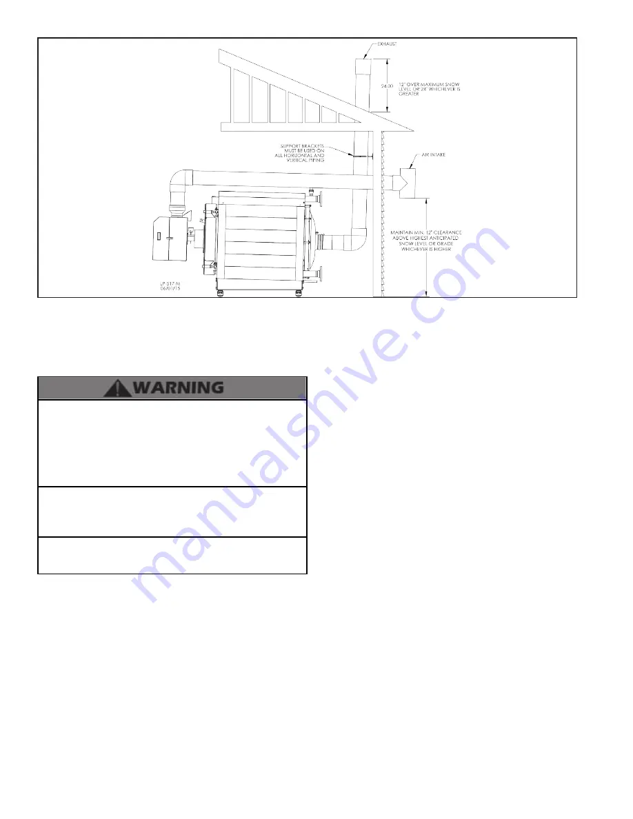
Figure 14 - Unbalanced Venting - Roof Exhaust and Sidewall Intake
NOTE:
This drawing is meant to demonstrate system venting
only. The installer is responsible for all equipment and detailing
required by local codes.
Ensure the terminations are screened to prevent blockage
caused by debris or birds.
All vent pipes must be glued, properly supported, and the
exhaust pitched a minimum of 1/4” per foot back to the boiler to
allow drainage of condensate. When placing support brackets
on vent piping, the first bracket must be within 1 foot of the
boiler and the balance of 4 foot intervals on the vent pipe.
Venting must be readily accessible for visual inspection from
the first three feet from the boiler.
Take extra precaution to adequately support the weight of vent
pipes terminating through the roof. Failure to properly support
roof terminated vent piping could result in property damage,
serious personal injury, or death due to flue gas leakage.
An unbalanced vent system can be installed ONLY when the
exhaust is in the vertical position. Failure to do so could result in
serious personal injury or death.
2. Room and Indoor Combustion Ventilation Requirements
When using an indoor combustion air installation, the
mechanical room MUST be provided with properly sized
openings, and/or be of sufficient volume to assure adequate
combustion air and proper ventilation for all gas fired appliances
in the mechanical room to assure adequate combustion air and
proper ventilation. The requirements shown here are for the
boiler only. Additional gas fired appliances in the mechanical
room will require an increase in the net free area and/or volume
to supply adequate combustion air for all appliances. This must
be done in accordance with the National Fuel Gas Code, NFPA
54 / ANSI Z223.1.
This boiler can be vented using mechanical room air only for
combustion. No combustion air openings are needed when the
boiler is installed in a space with a volume NO LESS than 50
cubic feet per 1,000 BTU/hr of all installed gas fired appliances
and the building MUST NOT BE of “Tight Construction”.
TIGHT CONSTRUCTION:
A building with less than .4 ACH
(air changes per hour). For buildings of “Tight Construction”,
provide air openings into the building from the outside.
Indoor and outdoor combustion air may be combined by
applying a ratio of available volume to required volume times
the required outdoor air opening(s) size(s). This must be done
in accordance with the National Fuel Gas Code, NFPA 54 /
ANSI Z223.1.
1. If air is taken directly from outside the building with no duct,
provide two permanent openings to the mechanical room
each with a net free area of one square inch per 4000 BTU/hr
input. See Figure 15.
2. If combustion and ventilation air is taken from the outdoors
using a duct to deliver the air to the mechanical room, each of
the two openings should be sized based on a minimum free
area of one square inch per 2000 BTU/hr input. See Figure 16.
3. If air is taken from another interior space combined with the
mechanical room:
a. Two spaces on same story: Each of the two openings
specified should have a net free area of one square inch for
each 1000 BTU/hr input, but not less than 100 square inches.
b. Two spaces on different stories: One or more openings
should have a net free area of two square inches per 1000
BTU/hr.
See Figure 17 for reference.
4. If a single combustion air opening is provided to bring
combustion air in directly from the outdoors, the opening
must be sized based on a minimum free area of one square
inch per 3000 BTU/hr. This opening must be located within 12”
of the top of the enclosure. See Figure 18.
Combustion air requirements are based on the latest edition
of the National Fuel Gas Code, NFPA 54 / ANSI Z223.1, CGA
Standard CAN/CSA B149.1 in Canada. Check all local code
requirements for combustion air.
All dimensions based on net free area in square inches. Metal
louvers or screens reduce the free area of a combustion air
opening a minimum of approximately 25%. Check with louver
Содержание WBCETNG1000
Страница 14: ...WHL 038 Rev 1 29 16 14 Figure 6 Specifications and Dimensions NOTE All Dimensions Are Approximate ...
Страница 35: ...WHL 038 Rev 1 29 16 35 Figure 24 CascadeTermination Plug Detail Figure 25 Cascade Master and FollowerWiring ...
Страница 36: ...WHL 038 Rev 1 29 16 36 Figure 26 Internal Connection Diagram ...
Страница 65: ...WHL 038 Rev 1 29 16 65 Figure 44 Exterior Replacement Parts ...
Страница 66: ...WHL 038 Rev 1 29 16 66 Table 27 Optional Jacket Replacement Parts Part 15 Installing the Optional Jacket ...
Страница 73: ...WHL 038 Rev 1 29 16 73 Maintenance Notes ...