


WHL-038 Rev. 1.29.16
33
Failure to use the correct sensor may result in tank
temperature being either above or below set point, and
could result in decreased performance, substantial property
damage, or heightened risk of injury or death due to scalds.
Caution should be used to ensure neither of these terminals
becomes connected to ground.
NOTE:
If sensor wires are located in an area with sources of
potential electromagnetic interference (EMI), the sensor
wires should be shielded, or the wires routed in a grounded
metal conduit. If using shielded cable, the shielding should be
connected to the common ground of the boiler.
I. Optional 0-10 Volt Building Control Signal
1. A signal from a
building management
system may be
connected to the boiler
to
enable
remote
control. This signal
should be a 0-10 volt
positive-going
DC
signal.
When
this
input is enabled using
the installer menu,
a
building
control
system can be used to
control the set point
temperature of the
boiler. The control
interprets the 0-10
volt signal as follows;
when the signal is
between 0 and 1 volts,
the boiler will ignite.
As the signal continues to rise towards
its maximum of 10 volts, the boiler will
increase in either set point temperature
or firing rate depending on the setting
of function 17 in the Installer Menu. See
this manual for details on the setting of
function 16 and 17 for this option.
2. Connect a building management
system or other auxiliary control signal
to the terminals marked 17, 0-10 VOLT
+ and 16, 0-10 VOLT – in the electrical
junction box (shown in Figure 22).
Caution should be used to ensure that
the 0-10 VOLT + connection does not
become connected to ground.
J. Optional High Gas Pressure
Switch
1. If an optional high gas pressure
switch is used, it should be installed on
the outlet side of the gas valve. This is
normally closed and will open if the
pressure goes above 20” w.c. on the
outlet side.
2. Locate the two pigtails hanging from
the electrical box inside of the boiler cabinet. Remove and
K. Optional Low Gas Pressure Switch
1. If an optional low gas pressure switch is used, it should be
installed on the inlet side of the gas valve. This is normally closed
and will open if the pressure goes below 1” w.c. on the inlet side.
2. Locate the two pigtails hanging from the electrical box inside
of the boiler cabinet. Remove and discard the jumper plug from
one of the unused pigtails.
3. Connect the low gas pressure switch to the pigtail that you
removed the jumper plug from.
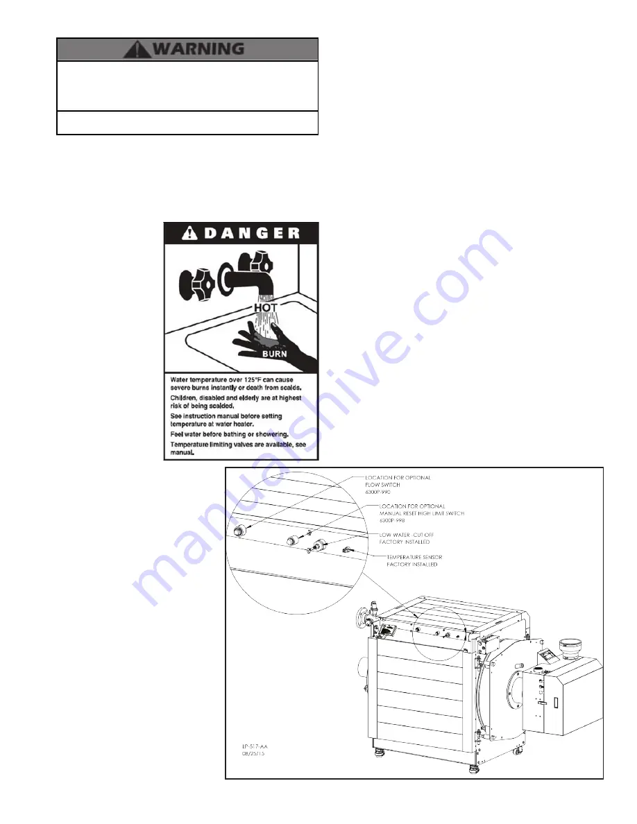
L. Optional Flow Switch
NOTE:
Follow the more detailed instructions included with the
flow switch kit for proper installation steps.
1. Attach the correct flow paddle to the flow switch.
2. Thread flow switch into the fitting provided on the manifold
using teflon thread tape.
Make certain the FLOW arrow points
in the correct direction.
3. Locate the two red wires at the boiler and connect them to the
flow switch as described in the flow switch instructions.
4. When installation is complete, power up the boiler and use
the control to access installer parameter #20 and change the
default value to FLOW SWITCH. When done, create a demand
and observe boiler function to verify the installation is working
properly.
NOTE:
The flow switch requires a minimum flow rate of 21 GPM
to activate the boiler. The sensitivity of the flow switch can be
adjusted. See manufacturer’s instructions for details.
M. UL353 Internal Low Water Cut-Off (Factory Installed)
The supplied internal Low Water Cutoff (LWCO) meets UL 353
requirements to function as a safety, locking out the boiler when
water level is inadequate for safe operation.
Figure 23 - Boiler Manifold
discard the jumper plug from one of the unused pigtails.
3. Connect the high gas pressure switch to the pigtail that you
removed the jumper plug from.
Содержание WBCETNG1000
Страница 14: ...WHL 038 Rev 1 29 16 14 Figure 6 Specifications and Dimensions NOTE All Dimensions Are Approximate ...
Страница 35: ...WHL 038 Rev 1 29 16 35 Figure 24 CascadeTermination Plug Detail Figure 25 Cascade Master and FollowerWiring ...
Страница 36: ...WHL 038 Rev 1 29 16 36 Figure 26 Internal Connection Diagram ...
Страница 65: ...WHL 038 Rev 1 29 16 65 Figure 44 Exterior Replacement Parts ...
Страница 66: ...WHL 038 Rev 1 29 16 66 Table 27 Optional Jacket Replacement Parts Part 15 Installing the Optional Jacket ...
Страница 73: ...WHL 038 Rev 1 29 16 73 Maintenance Notes ...