background image

50

Integrated Web Server

6.3  Using More than One Sensor (synchronization)

It may be necessary to use more than one weCat3D in an application. This is fundamentally possible, but it 
necessitates special wiring and sensor configuration depending on sensor array and how the sensors are 
used.

 Note!
The master (sensor 1 in this example) has to be in the “Encoder”, “Internal” or “Software” 
profile mode, and the slave (sensor 2 in this example) has to be in the “syncIN” sync mode.

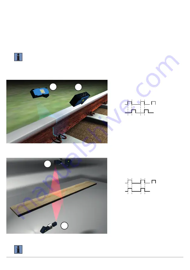
Example 1: Time-shifted measurement for extending the measuring range while avoiding reciprocal influence 
of the sensors despite overlapping of the laser lines.

2

1

Figure 6: Sample Application, Rail Head Measurement

Example 2: Simultaneous measurement:

1

2

Figure 7: Sample Application, Thickness Measurement for Wooden Floorboards


NOTE!
The hardware trigger must have a pulse width of at least 10 µs.

Sample configuration:
Master, SyncOut (default setting I/O3)
connected to slave, SyncIn (default setting  
I/O4).

Sensor 1

Sensor 2

Exposure Time

Sensor 1:
Sync mode (internal/encoder/software)
Exposure time: 200 µs
Sync out delay: 200 µs

Sensor 2:
Sync mode (syncIN)
Exposure time: 200 µs

Sample configuration:
Master, SyncOut (default setting I/O3)
connected to slave, SyncIn (default setting  
I/O4).

Sensor 1

Sensor 2

Exposure Time

Sensor 1:
Sync mode (internal/encoder/software)
Exposure time: 200 µs
Sync out delay: 0 (default setting)

Sensor 2:
Sync mode (syncIN)
Exposure time: 200 µs

Содержание weCat3D MLSL1x1

Страница 1: ...MLWL 2D 3D Profile Sensors Operating Instructions Translation of the Original Operating Instruction Subject to change without notice Available as PDF version only Status 28 06 2018 Version 1 2 0 www w...

Страница 2: ...12 3 2 Dimensional Drawings 18 3 3 Connection Diagram 24 3 4 Layout 25 3 5 LED Display 26 3 6 Control panel 27 4 Transport and Storage 27 4 1 Transport 27 4 2 Scope of Delivery 27 4 3 Storage 27 5 In...

Страница 3: ...D Display 51 7 1 Settings 52 7 2 Run 52 7 3 Encoder 53 7 4 Display 53 7 4 1 Rotate 53 7 4 2 Intensity 53 7 4 3 Mode 53 7 5 Configuration 54 7 5 1 Load 54 7 5 2 Save 54 7 6 Interface 54 7 6 1 IP adress...

Страница 4: ...recautions and warnings are emphasized by means of symbols and attention getting words Safe use of the product is only possible if these safety precautions and warnings are adhered to The safety preca...

Страница 5: ...s other than those intended Use by untrained personnel Use of unapproved replacement parts Unapproved modification of products These operating instructions do not include any guarantees from wenglor w...

Страница 6: ...ded into two performance classes weCat3D MLSL and weCat3D MLWL Whereas the weCat3D MLSL provides for high performance in standard applications with its compact design the weCat3D MLWL assures maximize...

Страница 7: ...he intended purpose may lead to hazardous situations Instructions regarding use for intended purpose must be observed 2 3 Personnel Qualifications Suitable technical training is a prerequisite In hous...

Страница 8: ...HLUNG NICHT IN DEN STRAHL BLICKEN ODER DIREKT MIT OPTISCHEN INSTRUMENTEN BETRACHTEN LASER KLASSE 2M EN60825 1 2007 E 25 W m 400 460 nm LASER RADIATION DO NOT STARE INTO BEAM Complies with 21 CFR 1040...

Страница 9: ...or NO operation yes PNP NPN push pull yes Short circuit proof yes Reverse polarity protected yes Overload proof yes Interface Ethernet TCP IP Transmission speed 100 1000 MBit s Protection class III I...

Страница 10: ...246 m Temperature drift 2 m K 3 m K 10 m K 20 m K Linearity deviation 18 m 30 m 95 m 200 m 0 05 Service life Tu 25 C 20 000 h max Ambient Light 5 000 Lux Order No Technical Data MLSL2x5 MLSL2x6 Optica...

Страница 11: ...025 Service life Tu 25 C 20 000 h max Ambient Light 5 000 Lux Order No Technical Data MLWL2x1 MLWL2x2 MLWL2x3 MLWL2x4 MLWL2x5 Optical Data Working range Z 120 300 mm 120 470 mm 300 1000 mm 600 2000 mm...

Страница 12: ...Red 660 nm 2M 3 Laser Blue 405 nm 2M 4 Laser Red 660 nm 3R 5 Laser Blue 405 nm 3R 7 Laser Blue 450 nm 3B Only available for weCat3D MLWL and MLSL2 3 1 Fields of Vision weCat3D MLSL weCat3D MLSL1x1 MLS...

Страница 13: ...0 300 100 50 0 50 100 X mm Z mm MLSL1x3 150 weCat3D MLSL1x4 200 400 500 100 600 200 100 0 100 200 X mm Z mm MLSL1x4 300 weCat3D MLSL2x5 400 300 200 1200 1300 1100 1000 1400 100 1500 200 300 400 0 100...

Страница 14: ...500 250 X mm Z mm weCat3D MLWL weCat3D MLWL1x1 40 30 20 120 130 110 100 140 10 150 20 30 40 0 10 10 20 30 40 X mm Z mm MLWL1x1 90 80 70 60 50 weCat3D MLWL1x2 80 60 40 240 260 220 200 280 20 300 40 60...

Страница 15: ...x3 MLWL1x3 0 50 100 150 150 100 50 X mm Z mm weCat3D MLWL1x4 MLWL1x4 0 100 200 300 300 200 100 X mm Z mm weCat3D MLWL1x5 400 300 200 1200 1300 1100 1000 1400 100 1500 200 300 400 0 100 100 200 300 400...

Страница 16: ...00 100 50 0 50 100 X mm Z mm MLWL2x1 150 weCat3D MLWL2x2 200 400 500 100 600 200 100 0 100 200 X mm Z mm MLWL2x2 300 weCat3D MLWL2x3 400 300 200 1200 1300 1100 1000 1400 100 1500 200 300 400 0 100 100...

Страница 17: ...17 2D 3D Profile Sensors weCat3D MLWL2x4 MLWL2x4 0 250 500 750 750 500 250 X mm Z mm weCat3D MLWL2x5 MLWL2x5 0 600 900 1200 1500 1800 2100 2400 300 2700 3000 300 600 900 900 600 300 X mm Z mm...

Страница 18: ...18 Technical Data 3 2 Dimensional Drawings weCat3D MLSLxxx weCat3D MLSL1xx weCat3D MLSL2xx 1 only MLSL2 with laser class 3R and 3B...

Страница 19: ...19 2D 3D Profile Sensors weCat3D MLWLxxx weCat3D MLWL1x1 weCat3D MLWL1x2...

Страница 20: ...20 Technical Data weCat3D MLWL1x3 weCat3D MLWL1x4 1 recommended mounting position based on the sensor s center of gravity 1 recommended mounting position based on the sensor s center of gravity...

Страница 21: ...21 2D 3D Profile Sensors weCat3D MLWL1x5 weCat3D MLWL2x1 1 recommended mounting position based on the sensor s center of gravity...

Страница 22: ...22 Technical Data weCat3D MLWL2x2 weCat3D MLWL2x3 1 threaded on both ends 1 threaded on both ends...

Страница 23: ...23 2D 3D Profile Sensors weCat3D MLWL2x4 weCat3D MLWL2x5 1 recommended mounting position based on the sensor s center of gravity 1 recommended mounting position based on the sensor s center of gravity...

Страница 24: ...ageable Magnet activation Input confirmation Contactor Monitoring Encoder A A TTL Encoder B B TTL Black Brown Red Orange Yellow Green Blue Violet Grey White Pink Green Yellow Supply Voltage Supply Vol...

Страница 25: ...D MLSL 1 2 3 4 5 6 7 8 weCat3D MLWL Power supply plug connector digital I O Connection Socket Ethernet External 24 V laser shutdown only for MLSL2 with laser class 3R or 3B LED display Control panel d...

Страница 26: ...blinking Communication 10 Mbit Off No Ethernet device connected 78 MS Module Status Green Device operative Green blinking Standby Red blinking Device error Red Device error Off Device doesn t start u...

Страница 27: ...damage in transit 4 2 Scope of Delivery weCat3D Sensor Laser LED Warnings Quickstart instructions Mounting Set 4 3 Storage The following points must be taken into condition with regard to storage Do n...

Страница 28: ...allic connection between the sensor housing and the mounting base A cooling unit should be used as of an ambient temperature of 45 C or in the event that the sensor is mounted in a thermally insulated...

Страница 29: ...heir large dynamic range weCat3D Sensors continue to provide measured values even in the event of tilting Tightening torques must be complied with in order to assure error free operation The respectiv...

Страница 30: ...ementary Products wenglor offers Connection Technology for field wiring Suitable Mounting Technology No 343 Suitable Connection Technology No 50 87 S80 S89 89 S74 Switch ZAC45FN01 Cooling unit Protect...

Страница 31: ...on Cable M12 8 pin to RJ45 ZC1V001 straight 2 m ZAV50R502 straight 5 m ZC1V002 straight 10 m ZC1V013 straight 30 m ZC1V009 angled 2 m ZC1V010 angled 5 m ZC1V011 angled 10 m ZC1V003 straight 5 m ZC1V01...

Страница 32: ...0 m ZDCL004 angled 2 m ZDCL005 angled 5 m ZDCL006 angled 10 m Connection Cable M12 8 pin to RJ45 ZC1V001 straight 2 m ZAV50R502 straight 5 m ZC1V002 straight 10 m ZC1V013 straight 30 m ZC1V009 angled...

Страница 33: ...th laser class 3R and 3B are additionally equipped with 24 V laser shutdown see section 3 3 Connection Diagram page 24 Laser shutdown must be supplied with 24 V operating voltage to this end Switching...

Страница 34: ...t IP address 192 168 100 001 Subnet mask 255 255 255 000 The network part of the sensor s IP address must coincide with the network part of PC s IP address but the device part of the address must be d...

Страница 35: ...nalysis Operating mode Profile Sensor Profile Sensor Profile Measuring rate Hz 200 175 Signal selection Strength Strength Exposure time s 150 150 Field of vision pix Offset X 0 0 Width X 1280 2048 Off...

Страница 36: ...and save them directly at the PC Note The website has been optimized for the following web servers Firefox 51 Chrome 49 IE11 Deviations may result in erroneous displays 6 1 Accessing the Integrated W...

Страница 37: ...e laser activated laser on deactivated laser off Measuring rate Left momentary measuring rate Right maximum possible measuring rate with selected measuring range and exposure time calculated value may...

Страница 38: ...fe use the sensor within the specified temperature range only NOTE As of an internal temperature of 60 C the sensor is in its critical temperature range Encoder Left HTL encoder counter rotary encoder...

Страница 39: ...ss ranges can be entered to the IP Address Subnet Mask and Standard Gateway fields These addresses permit operation as well as communication between the sensor and your network PC CAUTION If you don t...

Страница 40: ...in order to protect the display Mode Selection of various display modes for the run mode Network IP address subnet mask and MAC address are displayed I O status Display of input and output states Ana...

Страница 41: ...and doesn t influence the parameter settings The individual colors have the following meanings White Signal 1 Red Signal 2 only visible with corresponding software setting Yellow Signal strength sign...

Страница 42: ...s MLSL or 2048 columns MLWL in the X direction which are read out continuously As a default setting offset X has a value of 0 If this value is increased not all of the columns are read out but rather...

Страница 43: ...tion At a signal strength of less than 10 exposure time should be increased for an ideal profile At a signal strength of greater than 90 exposure time should be reduced for an ideal profile Laser This...

Страница 44: ...urface Signal width is not shown in the profile display First The first signal in the profile display of the integrated website is read out as signal 1 Last The last signal in the profile display of t...

Страница 45: ...ode syncIN The sensor is triggered externally via the Sync IN pin function e g by anoth er sensor or by an input signal Only one profile per input signal is recorded and transmitted Example with trigg...

Страница 46: ...n is saved New profiles are not recorded until the saved position has been passed Direction Sensor records profile in one direction of motion only Sync Mode Software The sensor is triggered by a softw...

Страница 47: ...2D 3D Profile Sensors 6 2 4 I O Settings Various pin functions can be selected for the 4 configurable inputs outputs Depending on the selected setting context menus offer corresponding selection optio...

Страница 48: ...ace Pin function Encod I1 I2 Input function for connecting an HTL 5 to 24 V A B channel rotary encoder This function must be set for I O1 and I O2 at the same time This function is only available for...

Страница 49: ...play menu Pin function Encod reset Input function for resetting the internal encoder counter to 0 Internal load Connects an internal resistor to the input pull down Internal load of 2 mA on off Input...

Страница 50: ...f the laser lines 2 1 Figure 6 Sample Application Rail Head Measurement Example 2 Simultaneous measurement 1 2 Figure 7 Sample Application Thickness Measurement for Wooden Floorboards NOTE The hardwar...

Страница 51: ...r Type Prod Version Serial Number Info Reboot Password Reset R for Reboot R for Reset except network settings Enable Disable Change Encoder Rot Direction Encod Reset Configuration Interface Ethernet I...

Страница 52: ...menu by pressing any key NOTE If no settings are adjusted in the configuration menu for a period of 30 seconds the sensor is automatically returned to the display mode The sensor accesses the last us...

Страница 53: ...ver 3 Back 7 Run Normal Power Saver Screensaver Display intensity is set to the middle value If no keys are pressed for a period of one minute the display is switched off and is switched back on as so...

Страница 54: ...rd Set 1 Set 2 3 Back 7 Run Standard Set 1 Set 2 Sensor settings are saved under Standard Sensor settings are saved under Set 1 Sensor settings are saved under Set 2 7 6 Interface Ethernet Settings fo...

Страница 55: ...network menu without saving the entered IP address N The subnet mask the standard gateway and the TCP IP port can be changed using the same procedure as for the IP address 7 6 2 MAC address MAC addres...

Страница 56: ...ent that technical problems should occur and when contacting Technical Support with questions 7 9 Restart Restart Restarting the sensor Press R for restart R Restarting of the sensor can be forced by...

Страница 57: ...rd function is deactivated upon shipment from the factory Passwords can be selected within a range of 0000 to 9999 It must be assured that the selected password is noted before any changes occur If th...

Страница 58: ...nnection technology MLSL1 MLSL2 system overview External 24 V laser shutdown Default settings direction of rotation signal selection Note regarding programming interfaces Web server optimization Web s...

Страница 59: ...59 2D 3D Profile Sensors 10 2 EU Declaration of Conformity The EU declaration of conformity can be found on our website at www wenglor com in the product s separate download area...

Отзывы: