


ADJUSTMENTS
1. Turn off and disconnect the machine from the power source.
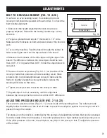
2. Remove the screw and washer securing the drum cover and
lift the cover open.
3. There are two screws (Fig. 22 - 1) on both ends of the drum.
To increase the roller pressure, evenly tighten all four Phillips
screws by rotating them clockwise in small increments. To
decrease the roller pressure, evenly loosen all four Phillips
screws in small increments.
4. To test the adjustments, turn on the machine and sand a scrap piece of workpiece. If the workpiece
slips on the conveyor belt, increase the pressure by rotating the four screws one turn clockwise.
If the workpiece tends to kick back, reduce the pressure by rotating the four screws one turn
counterclockwise.
5. Repeat until roller pressure has been properly adjusted. Close the drum cover and replace the
washer and cap screw.
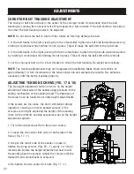
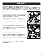
ADJUSTING THE STOP SCREW (FIG. 23)
The height adjustment stop, controlled by the protrusion of
the Phillips head screw through the bottom of the frame,
prevents the sanding drum from contacting the conveyor belt.
If necessary, re-adjust the height adjustment stop screw as
follow:
1. Turn off and disconnect the machine from the power source.
2. Loosen the height adjustment lock knob and raise the
sanding drum using the height adjustment wheel.
3. Loosen the hex nut on the stop screw and adjust the height of the screw (Fig. 23 - 1) to protrude
above the frame higher than 1/4 inch.
4. Tighten the hex nut and lower the sanding drum until the motor mount frame touches the top of
the stop screw.
5. Check that the bottom of the sanding drum is at least 3/16” above the surface of the conveyor belt.
If the distance is too close, repeat the steps above to re-adjust as necessary.
1
1
1
Fig. 22
Fig. 23
24
Содержание 65911
Страница 35: ...35 NOTES ...
Страница 36: ...THANKS FOR REMEMBERING ...