


ADJUSTMENTS
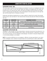
CONVEYOR BELT TRACKING ADJUSTMENT
The conveyor belt should track in the center of the conveyor table. Occasionally check the belt
tracking by running the conveyor belt at high speed for a few minutes. If the belt shifts to one side or
the other, the belt tracking needs to be adjusted.
NOTE:
Do not allow the belt to track off the rollers as this may damage the belt.
1. If the belt tracks to the left (viewing from the infeed side), tighten the left side tensioning screw by
rotating it clockwise while holding its nut in place. This will make the belt shift to the right side.
2. If the belt tracks to the right (viewing from the infeed side), tighten the right side tensioning screw
by rotating it clockwise while holding its nut in place. This will make the belt shift to the left side.
3. Let the conveyor belt run for a few minutes to check the belt tracking. Re-adjust as necessary.
NOTE:
The tracking adjustments may not be apparent immediately. Make small corrections of
approximately 1/4 turn increments to the tensioning knob and evaluate the results. Re--adjust as
necessary until the belt is tracking properly.
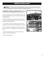
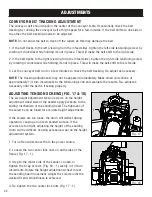
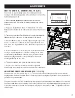
ADJUSTING TENSION SCREWS (FIG. 17 & 18)
The six height adjustment tension screws on the height
adjustment wheel side of the sander apply pressure to the
sliding mechanism of the sanding head. The tightness of
the screws can be tuned for accurate height adjustments.
If the screws are too loose, the drum will deflect during
operation, causing an uneven sanded surface. If the
screws are too tight, adjusting the height of the sanding
drum will be difficult, causing excessive wear on the height
adjustment system.
1. Turn off and disconnect from the power source.
2. Loosen the two center lock nuts on both sides of the
frame (Fig. 17 - 1).
3. Step to the motor side of the sander. Loosen or
tighten the 6 cap screws (Fig. 18 - 1) evenly in 1/4 turn
increments. Rotate the height adjustment wheel to test
the sanding head movement. Adjust the screws until the
desired fit and smoothness is achieved.
4. Re-tighten the two center lock nuts (Fig. 17 - 1).
1
1
1
1
Fig. 17
Fig. 18
22
Содержание 65911
Страница 35: ...35 NOTES ...
Страница 36: ...THANKS FOR REMEMBERING ...