The Weir Group PLC
Weir Industrial Gateway setup guide rev 0.5
Copyright © Weir Minerals Australia Ltd 2017. Commercial in Confidence. All rights reserved.
Page
42
of
46
14.8.313.8.3
Installation
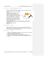
1. Clean shaft and bearing housing mount points of all slurry/debris
2. Loosely mount the target on the shaft.
3. Mount the sensor bracket onto the bearing assembly
4. Loosely secure the speed sensor into the sensor bracket
5. Align the speed sensor and the shaft target bracket so that the speed sensor is
directly above the target
6. Tighten both the target collar to the shaft and the lateral adjustment of the speed
sensor
7. Adjust the vertical motion of the speed sensor so that the gap is no more than 2mm
and tighten
8. Rotate the shaft to the edge of target and measure the gap. Ensure it is no more than
1mm and that it is not touching the corner.
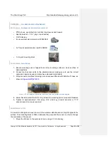
9. Connect the speed sensor to the test box. Rock the shaft back and forth, ensuring
that the indicator LED on the test box illuminates each time the target passes under
the sensor
10. Remove the test box from the sensor and connect the regular cable
11. Wrap connector interface with protective tape (Nitto No.15)
1514
Cleaning and Maintenance
The enclosure of the system is able to withstand slurry. This slurry should be removed
periodically with the use of water and a stiff brush. The use of pressurized water can also used to
clean the system.
There are no user serviceable parts inside the system. Technical support issues with this system
are available at:
Attn: Richard Smith
Sanmina
Unit 3, Cherrywood, Chineham, Basingstoke, UK RG24 8WF
United Kingdom
Telephone: +44 1256 637371
1615
Regulatory Compliance
The Weir Industrial Gateway system comprising of the PSM, MPM, and RSP are designed
and tested to comply with/meet the following standards:
16.115.1
Electromagnetic Compatability
o
FCC Part 15 Subject B class A
o
CISPR 22 Class A, EN55022 Level B
o
ICES-003 Class A
o
AS/NZS CISPR 32:2013

