The Weir Group PLC
Weir Industrial Gateway setup guide rev 0.5
Copyright © Weir Minerals Australia Ltd 2017. Commercial in Confidence. All rights reserved.
Page
40
of
46
14.6.213.6.2
Hazards
-
No task specific hazards of note
14.6.313.6.3
Installation
1. Ensure mounting puck/location surface is clean and free of debris/particles
2.
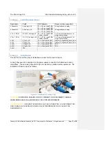
Fasten the RTD’s to the mount locations specified in section x.x
3. Screw cap-screw into mounting puck
4.
Tighten to approximately 3 Nm using 3/16” allen key
14.6.413.6.4
Removal
1. Release cap screw and remove sensor from mounting point
2. Install screw back into mounting hole to prevent slurry/crud from entering thread
14.713.7
Gland Water Flow Meter and Pressure Transducer
14.7.113.7.1
Equipment and materials required
• Minimum recommended PPE : gloves, eye protection, hard hat, long sleeves and
trousers
• Spanner/wrench to suit pipe fittings
• 1 ¼” open end spanner/wrench (for Pressure transducer)
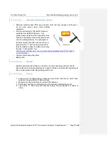
• 1x Flow Meter (part # xxxxxxx)
• 1x Pressure Tranducer (part # xxxxxxxx)
• Protective tape – Nitto Self-fusing Butyl Rubber Tape – No.15
• Plumbers thread tape
14.7.213.7.2
Possible Hazards
-
Water within the gland supply system may be at elevated pressure, enough to cause
eye damage if accidentally directed into the eye
-
Gland water supply is not likely potable water hence should not be ingested or
allowed to come into contact with the face
14.7.313.7.3
Installation
1. Ensure the gland supply is depressurised and the pump is not running
2. The pressure transducer and flow meter must be installed in series with the gland
water supply
3. Fittings to install the pressure and flow sensors are site specific and not supplied.
These should have been identified in the site survey and purchased ahead of
time. This will include a suitable T fitting for the pressure sensor.
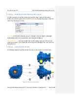
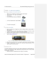
4. The suggested installation location is after an isolation valve (shown in image
below).
5. Connect pressure and flow sensors to main cable harness.
6. Wrap connector interfaces with protective tape (Nitto No.15).

