background image

11


5 | Purpose and Version 

5  Purpose and Version 

5.1 

Purpose of the Coolant 
Heater 

Webasto coolant heaters are used in connection 

with the vehicle’s own heating system 


to heat the  cab 


to defrost vehicle  windows 


to preheat water-cooled  engines 


to heat boats and motorhomes (recreational 

vehicles) 

The water heater operates independently of the en- 

gine and is connected to the cooling system, the fuel 

system and the electrical systems of the vehicle. 

5.2 

Version Thermo Top EVO 

Thermo Top EVO D 

Water heater utilizing diesel fuel. 

6  Installation Example 

6.1 

Safety Information 


NOTE 

The water heater must be installed outside 

the passenger cabin. 
The requirements of the latest version of 

Hazmat regulations must also be observed 

for the installation of the heater into 

vehicles used to transport hazardous sub- 

stances 

6.2 

Installation Location and 
Position 


NOTE 

If the vehicle manufacturer has issued spe- 

cific installation instructions, they must be 

followed. 

The heater must be installed in as low a position as 

possible to allow the heater and circulating pump to 

be bled automatically. This is particularly important 

as the circulating pump is not self-priming. 

The installation must be performed in accordance 

with the installation instructions provided in this 

manual. 

6.2.1


Model plate 

The heater model plate must be positioned so that it 

cannot be damaged and must be clearly legible when 

the heater is installed (otherwise a duplicate model 

plate must be used). Inapplicable years must be 

removed from the model  plate. 

6.2.2


CE Mark 

The Thermo Top Evo water heater carries the CE 

mark since it complies with the regulations in force. 

The heater satisfies the requirements of class A. As a 

result, the following supplement  applies: 

Installation in the engine compartment provides suf- 

ficient screening of radio interference. 

Содержание thermo top evo

Страница 1: ...r and other combustible matter The heater must be switched off when loading or unloading flammable materials to prevent the risk of explosion Webasto heating and cooling systems require qualified and or professional installation and repair technicians Warranty shall be void if not installed by a certified or trained in staller repair technician who has successfully completed the factory training c...

Страница 2: ... 15 7 1 System Connections 15 7 2 Heater Connections 15 7 3 CoolantSystemConnections 16 7 4 Circulation Pump Installation 17 7 5 InspectingtheCoolant System 17 8 Fuel Supply 18 8 1 ExtractingFuelfromaFuel Tank 18 8 2 Fuel Standpipe Installation 18 8 3 Fuel system overview 21 8 4 Fuel Lines 22 8 5 Fuel Filter 23 8 6 Fuel Metering Pump 23 9 Combustion Air System 24 9 1 General 24 9 2 Combustion AirS...

Страница 3: ...shop manual and the installation instructions The year of initial start up must be permanently marked on the type label by removing the inapplicable year s 1 3 Safety During Operation WARNING Danger of explosion In environments with combustible vapors flammable dust and hazardous goods such as fuel stations tank facilities fuel store coal bunkers timber yard or grain ware houses Do not switch on o...

Страница 4: ...s ongoing product improvement we encourage our customers to write to us with their comments or criticisms concerning this manual and the heater installation in general Please write to us at Webasto Thermo Comfort North America Inc Technical Documentation Group 15083 North Road Fenton MI 48430 You are also invited to fill out our online questionnaire concerning our technical documentation and web s...

Страница 5: ...ot carried out by a Webasto service workshop Use of non original spare parts Conversion of the heater without permission from Webasto 2 3 Using This Document Read and understand these Installation Instructions before installing the heater WARNING Indicates a potentially hazardous situation which if not avoided COULD result in death or serious injury CAUTION Indicates a potentially hazardous situat...

Страница 6: ...ect in the case of danger or emergency Cables damaged from sharp edges can cause short circuits 3 2 1 Parts of the vehicle body and other components in the immediate vicinity of the heater must be protected against excessive heat and the danger of contamination by fuel or oil 3 2 2 The internal combustion heater must not pose a fire hazard even when overheated This requirement is deemed to have be...

Страница 7: ...ehicle through ventilation devices hot air inlets or open windows 3 5 Combustion Air Inlet 3 5 1 The air for the combustion chamber of the heater must not be extracted from the passenger cabin of the vehicle 3 5 2 The air inlet must be positioned in such a way that it cannot be obstructed by other objects 3 6 Water Inlet 3 6 1 The supply of water to be heated must be protected against freezing wit...

Страница 8: ...within the vehicle must be positioned or protected in such a way as to exclude all risk of injury or damage caused by direct contact 3 7 2 The water outlet hose must be protected so that it cannot be obstructed by other objects or the flow of water through the hoses ...

Страница 9: ... F 40 to 80 C Storage 40 to 248º F 40 to 120 C Metering pump Operation 40 F to 86 F 40 to 30 C Storage 40 F to 194 F 40 to 90 C Perm operating pressure heat medium 36 25 PSI 2 5 bar Minimum quantity of coolant circuit 1 06 gal 4 l Minimum flow rate for the heater 66 gal h 250 l h CO2 in exhaust gas perm function range 8 to 12 vol Dimensions of heater Tolerance 3 mm L Length 8 6 218 mm B Width 3 6 ...

Страница 10: ...10 4 Technical Data 4 3 Technical Data Enclosure Box NOTE Drawing not to scale Fig 1 Enclosure Box Dimensions 4 4 Technical Data Mounting Plate NOTE Drawing not to scale Fig 2 Mounting Plate front view ...

Страница 11: ...ances 6 2 InstallationLocationand Position NOTE If the vehicle manufacturer has issued spe cific installation instructions they must be followed The heater must be installed in as low a position as possible to allow the heater and circulating pump to be bled automatically This is particularly important as the circulating pump is not self priming The installation must be performed in accordance wit...

Страница 12: ...Fig 3 Thermo Top Evo Components 1 Combustion Air Fan 7 Exhaust Outlet 2 Water Inlet 8 Exhaust Gas Temperature Sensor 3 Water Outlet 9 Fuel Inlet 4 Circulation Pump 10 Air Inlet 5 Fuel Metering Pump 11 Control Unit 6 Combustion Chamber 12 Burner Motor ...

Страница 13: ... Positions 6 4 2 Standard Mounting Bracket The heater must be fastened on the bracket with at least 3 three M5 bolts torqued to 6 lb ft 8Nm The heater fastening screws are approved for bracket metal thickness of 0 06 in 0 12 in 1 5 mm 3 0 mm The following figure is an example of a Thermo Top Evo bracket Fig 6 Thermo Top Evo Standard Bracket Exploded View and Dimensions ...

Страница 14: ...n the frame consult the manufacturer for guidelines and restric tions Do not weld vehicle frame or flanges Fig 7 Mounting Hole Dimensions Enclosure Box Fig 8 Mounting Points Mounting Plate 11 8 in 300 mm 4 1 in 105 mm 9 6 in 244 mm 3 7 in 94 mm 0 3 in 7 5 mm ...

Страница 15: ... specifications The hoses must be routed without kinking and preferably uphill from the heater to ensure proper bleeding Fig 10 Typical Pre Heating System Configuration Separate the heater supply and return connections at the engine as far apart as is practical for optimum engine heating and heater performance when the heater is used for engine pre conditioning 1 Coolant Supply Con nection 2 Vehic...

Страница 16: ...age 15 Route coolant hoses in such a way to avoid kinks and pinches Be sure the hoses run slightly uphill from the heater to help in bleeding the coolant sys tem Secure hose connections using hose clamps NOTE When integrating the coolant hoses in the coolant circuit the correct direction of flow of the coolant must be ensured Use the coolant flow arrows on the heater when in stalling coolant hoses...

Страница 17: ... pump to the vehicle s coolant circuit The installation position of the circulation pump must be chosen so that the circulation pump is self bleeding It must be possible for the air trapped in the circulation pump to escape upward via the connection piece Incorrect installation can result in malfunction of the circulation pump 7 5 InspectingtheCoolant System After the heater and all coolant carryi...

Страница 18: ... fuel tank if in stalling a fuel standpipe After any drilling or cutting is performed clean and deburr the hole to eliminate potential leak paths Clean the installation surface of the tank extract ing device In installed position maintain a minimum dis tance of 1 in 25 mm between the standpipe and base of the fuel tank fuel delivery unit Position the tank extracting device vertically Use the speci...

Страница 19: ... smooth edges with emery cloth 3 determine length of standpipe when installed End should sit at least 25mm 1 above tank bot tom Cut off excess standpipe at a 45 degree angle Remove burrs 4 loosely assemble items 5 place sealing compound on threads of item 2 and thread into item 6 Tighten item 2 completely 6 slide standpipe into hole at angle Slip one shoulder of item 6 inside the hole as shown Fig...

Страница 20: ...l Supply 20 9 Pull up on the standpipe and tighten in place with the clamping nut item 1 Do not overtighten the nut to prevent the rubber washing becoming dis torted Fig 18 Standpipe Installation 4 Fuel Tank ...

Страница 21: ...m overview Fig 19 Fuel System Parameters 1 Fuel Line Coupler 5 Max Suction Height A 3 3 1m 2 Fuel Line 6 Max Suction Length A B 9 9 3m 3 Fuel Filter 7 Max Delivery Length C D 28 3 9m 4 Fuel Dosing Pump 8 Max Delivery Height D 9 9 3m ...

Страница 22: ...ot be damaged by flying road debris and high temperatures i e close to the ex haust line The fuel line must be secure at the con nections using hose clamps to prevent slipping NOTE Always cut fuel lines in such a way that you won t cause burrs Be sure to check for and remove burrs after each fuel line cut The correct procedure for connecting fuel lines is shown below Ensure that there are no leaks...

Страница 23: ...ng and shut off system This dry primeable solenoid style piston pump pumps the fuel from the vehicle fuel tank to the fuel connection piece of the heater via fuel lines Installation is usually carried out near the fuel tank The metering pump contains no pulsation damper The metering pump is connected to the control unit via the heater unit wiring harness and to an earthing point on the vehicle bod...

Страница 24: ...bustion air intake must route in such a way that the intake will not terminate in the vi cinity of the heater s or vehicle s exhaust pipe The combustion air intake opening has the fol lowing requirements It must be positioned in a cool place above the maximum permissible fording level of the vehicle in a location protected from spray It must not be possible for it to become clogged with dirt It mu...

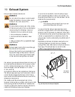
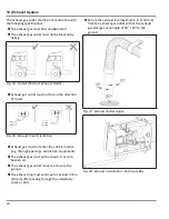
Страница 25: ...cated so that it cannot become clogged with snow or dirt The ex haust outlet must be unobstructed and must not be directed at vehicle parts The muffler and the exhaust pipe must not be fastened to temperature sensitive vehicle parts Suffi cient spacing at least 0 8 20mm to temperature sensitive components must be ensured Thermal in sulation of the exhaust pipe is permissible It is also recommended...

Страница 26: ...tion Exhaust gas must not enter the vehicle interior e g through openings ventilation equipment The exhaust gas must not be drawn in as com bustion air The exhaust gas outlet is not too close to the ground The exhaust line must continue for at least 3 8 in 10 mm after passing through the underbody cover or skirt Secure the exhaust line maximum 6 in 150 mm from the exhaust gas outlet so that the ex...

Страница 27: ...ys comply with legal requirements CAUTION All the cables and wires that are not re quired to be connected must be insulated against accidental shorting or grounding 11 1 Battery Connections WARNING All power connections must be fused within 14 in 356 mm of the battery The heater s power supply must be directly from the vehicle s batteries or main buss bar Power and ground to the heater must be ava...

Страница 28: ...o mount 2 Drill a in 19 mm hole for the switch 3 Route the harness between the heater and the switch secure the harness along its length with wire ties If possible use an existing hole in the bulkhead or drill a hole in a suitable location Pro tect the harness with a grommet at the bulkhead 4 Connect the electrical connector to the switch Always make sure there are no obstacles behind the mounting...

Страница 29: ...ation 4 Not used 4 Ambient temperature air heaters only For terminal removal use Molex terminal removal tool P N 11 03 0044 http www molex com aaOnly used in original equipment installations NOTE Always make sure there are no obstacles behind the mounting location prior to drilling NOTE Ensure good readability when selecting installation location NOTE Observe information on adhesive labels and col...

Страница 30: ...Optional Step To route wire harness through the mounting surface drill a 11 16 in 17mm hole Make sure to push harness through the hole before installing terminals into connector housing Secure the SmarTemp unit using the two sup plied 4 screws Apply the supplied Heater Off warning sticker in a highly visible location to the driver s area Observe the installation operating manual supplied for prope...

Страница 31: ...31 12 Wiring Diagrams 12 Wiring Diagrams 12 1 Thermo Top Evo with On Off switch Fig 33 Thermo Top Evo With On Off Switch ...

Страница 32: ...32 12 WiringDiagrams 12 2 Thermo Top EVO with SmarTemp 2 0 Fig 34 ThermoTop EVO with SmarTemp 2 0 ...

Страница 33: ...33 12 WiringDiagrams 12 3 Thermo Top Evo with SmarTemp 3 0 Fig 35 ThermoTop EVO with SmarTemp Control 3 0 and 3 0 Bluetooth ...

Страница 34: ...12 WiringDiagrams 34 12 4 Thermo Top EVO with Enclosure Box Fig 36 Thermo Top EVO with Enclosure Box on off switch ...

Страница 35: ...12 WiringDiagrams 35 12 5 Thermo Top EVO with Enclosure Box Fig 37 Tandem 717 wiring diagram SmarTemp 3 0 Thermo Top Evo left Air Top 2000STC right ...

Страница 36: ...Fan M2 Circulation Pump S1 Toggle switch or SmarTemp ON OFF operation X1 Plug con nector 10 pin Vehicle plug on item A2 X2 Plug con nector 2 pin Power supply on item A2 X3 Plug con nector 4 pin Overheat sensor and coolant temperature sensor on item A2 X4 Plug con nector 2 pin Circulation pump to control module X5 Plug con nector 2 pin Glow plug to control mod ule X6 Plug con nector 2 pin Exhaust t...

Страница 37: ...driveline loaded or unloaded suspension etc 4 Is the heater mounted in an acceptable position according to the limitations noted in this installation manual 5 Is the heater installed in a location that is protected from road debris and splash water or items stored in the same compartment 6 Is there sufficient clearance between the heater and the ground Coolant System Complete Yes No Comments 1 Is ...

Страница 38: ...nents and the battery 8 Ensure the battery is mounted securely and connections are prop erly tightened 9 Ensure the battery has a full charge Fuel Systems Complete Yes No Comments 1 Is the standpipe properly mounted in the fuel tank sealed structural integrity maintained 2 Validate that the standpipe does not interfere with the function of the fuel sending unit by checking the fuel gauge for prope...

Страница 39: ...he air intake system is securely fastened Heater Function Complete Yes No Comments 1 Ensure the heater starts and runs for a minimum of 20 minutes 2 Ensure vehicle blower operates as intended 3 Ensure warm air is blown out of interior vents after blower is activ ated 4 Ensure timer control element is functioning 5 Check and Modify CO2 setting as needed based on allowable alti tude limits See servi...

Страница 40: ...est PC Dia gnostics Prime the fuel line s until all of the air has been purged from the fuel lines Ensure that the fuel filter has been bled See Fuel Fil ter NOTE The standard duration stored in the Webasto Thermo Test software for fuel prime is sufficient for most vehicle models and heater applications If the lines cannot be successfully primed using Webasto Thermo Test software it may be necessa...

Страница 41: ...ons and fuses Loose contact on connections IMPORTANT After any correction of a defect a functional test must be performed NOTE Before each repair on the heater the fault memory must be read out with the Webasto Thermo Test PC Diagnosis Exist ing faults must be printed before deleting and made available to the Webasto Hotline or the Warranty Department At low temperatures and with no wind a minor a...

Страница 42: ...nks Check coolant level bleed coolant circuit if ne cessary Allow heater to cool down Check for failure codes and repeat as necessary Heater overheats Charge replace batteries Switch off heater momentarily and switch on again Heater expels black smoke from the exhaust Combustion air and or exhaust tube blocked Check combustion air intake and or exhaust tube The heater can be registered by visiting...

Страница 43: ...he PC Diagnostic Interface Kit comes complete with connecting hardware software and instructions Also available are several interface connectors for use with Webasto heaters equipped with internal diagnostics capabilities such as the Thermo Top Evo In addition to working with stored fault codes the PC Diagnostics Kit allows you to do several other functions such as reading values while the heater ...

Страница 44: ...flashes F01 1 flash No start after 2 attempts to start F02 2 flashes Flame failure F03 3 flashes Under voltage or over voltage F04 4 flashes Premature flame recognition F05 5 flashes Not used F06 6 flashes Coolant temperature sensor interrupt or temperature sensor short circuit F07 7 flashes Metering pump interrupt or metering pump short circuit F08 8 flashes Combustion air fan motor interrupt or ...

Страница 45: ... Heater Lock out Reset Procedure 1 Switch the heater ON 2 Within 10 seconds disconnect power from the heater unplug the wiring harness disconnect the battery remove the fuse 3 Wait 10 seconds 4 Switch the heater OFF 5 Reconnect power 6 Switch the heater ON 7 Rectify the cause of the fault NOTE In most cases a heater lockout can be removed using the procedure as stated above In faults where safety ...

Страница 46: ...15 NOTES NOTES ...

Страница 47: ......

Страница 48: ...Webasto Thermo Comfort N A Inc 15083 North Road Fenton MI 48430 Technical Assistance Hotline USA 800 860 7866 Canada 800 667 8900 5013388C Org 03 2019 Rev 11 2021 www webasto com www techwebasto com ...

Отзывы: