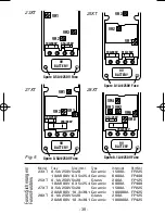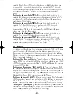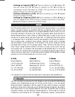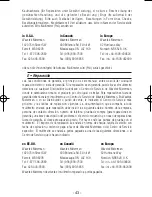
CALIBRATION
The procedure should be performed at an ambient temperature of 25°C ± 2°C, and at a
relative humidity of less than 80%. Allow the instrument to stabilize at this temperature
for a minimum of 30 minutes.
Warning:
Calibration should be performed by trained calibration personnel only.
Remove the back case (after turning off meter and removing test leads). Please refer
furtheron to figure 4.
VDC Calibration (all models):
❶
Set the Function/Range switch to the 200mV
position and push AC/DC button to select DC.
❷
Set the output of the DC calibrator for
190.0V ±0.02% and connect it to the “V
Ω
” and “COM” input terminals.
❸
Adjust VR1
until the display reads 190.0V ±1 digit.
Temperature Calibration (23XT - 28XT):
❶
Set the function/range switch to the
200°C position.
❷
Connect a K-type thermocouple and immerse it into a water/ice
mixture at 0°C. Let stabilize for 3 minutes.
❸
Adjust VR2 (VR6 on 28XT) until display
reads 00.0°C ±1dgt.
❹
Set function switch to 200°F position.
➎
Adjust VR3 (VR8 on
28XT) until display reads 32.0°F ±1dgt.
Capacitance calibration (25XT):
❶
Set the function/range switch to the 200pF
position.
❷
Adjust VR3 (on front of meter) until display reads 00.0.
❸
Set function
switch to 200nF.
❹
Connect a (discharged) standard capacitor of 100nF ±0.1nF to Cx
and COM or to Cx input slots.
➎
Adjust VR2 until display reads 100 ±1dgt.
Capacitance calibration (27XT):
❶
Set the function/range switch to the 2µF
position.
❷
Connect a (discharged) standard capacitor of 1.000µF ±1nF to Cx and COM
or to Cx input slots.
❸
Adjust VR2 until display reads 1.000 ±1dgt.
Capacitance calibration (28XT):
❶
Set the function/range switch to the 2nF
position.
❷
Adjust VR3 until display reads 0.000.
❸
Set function switch to 2µF.
❹
Connect a (discharged) standard capacitor of 1.000µF ±1nF to Cx and COM terminals.
➎
Adjust VR2 until display reads 1.000 ±1dgt.
Inductance calibration (27XT):
❶
Set the function/range switch to 2mH position.
❷
Adjust VR3 until display reads 0.000.
Frequency calibration (28XT):
❶
Set the function/range switch to the 200Hz
position.
❷
Set the output of the function generator to 100Hz ±0.02% and connect it to
the V-
Ω
and COM terminals.
❸
Adjust VR4 until display reads 100.0Hz ±1 digit.
D • Kalibrierung
Die Kalibrierung soll bei 25°C ± 2°C, und einer relativen Feuchte von <80%
vorgenommen werden. Instrument min. 30 Minuten lang stabilisieren lassen.
Warnung: Kalibrierung soll nur durch befugtes Fachpersonal vorgenommen werden.
Geräterückwand losschrauben und abheben (Gerät ausgeschaltet und Meßkabel
entfernt). Siehe weiterhin Fig. 5. .
VDC Kalibrierung (alle Modelle):
❶
Funktionsschalter auf 200mV Position
stellen und AC/DC Taste drücken um DC zu wählen.
❷
Ausgang des DC Kalibrators
auf 190.0V ±0.02% einstellen und mit “V
Ω
” und “COM” Eingängen verbinden.
❸
- 39 -
23XT-28XT.Man.08.00 9/11/00 7:03 PM Page 42
Содержание METERMAN 23XT
Страница 47: ... 45 ...

