- 15 -
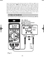
lead to the V•
Ω
Input and the black test lead to the COM Input.
❷
Set the
Function/range switch to
position.
❸
Apply probe tip of red lead to the anode
and of black lead to the cathode of the diode.
❹
The meter’s display indicates the
forward voltage drop (approximately 0.6V for silicon diode or 0.4V for germanium
diode). Meter will display overload condition for an open diode.
➎
Reverse test lead
connections to the diode to perform a reverse bias test. Overload indicates a good diode.
Notes: Overload condition for both reverse and forward bias tests indicate an open
diode. A low voltage reading for both bias tests indicates a shorted diode. Bipolar
transistor junctions may be tested in the same manner described above.
D • Dioden- und Transistortest
Der Diodentest zeigt den Spannungsabfall über den Diodendurchgang
❶
Rotes
COM
V-
Cx
Lx
mA Cx Lx
20A
1000
750
200
200m
20
20M
2
FUSED
FUSED
MAX
CAT.
II
27XT
H
V
F
1000V
750V
200mA MAX
MAX
CMOS
DC/AC
MAX
mV
HI/LO
ON/OFF
LOGIC
TTL
Hz
2000
200
2k
20k
200k
20M
M
2M
2000
20m
20
200m
2
2n
20n
2m
20m
10A
200
2
20
200m
2m
20A/30sec
A
Anode
Cathode
2
3
550 - 900mV
good/gut/bien/bon
Reverse Bias Test
good/gut/
bien/bon
bad/schlecht/mal/
mauvais
bad/schlecht/
mal/mauvais
<1V
Anode
Cathode
1
red
rot
roja
rouge
red
rot
roja
rouge
4
5
Fig. 4
23XT-28XT.Man.08.00 9/11/00 7:03 PM Page 18
Содержание METERMAN 23XT
Страница 47: ... 45 ...

