5-13
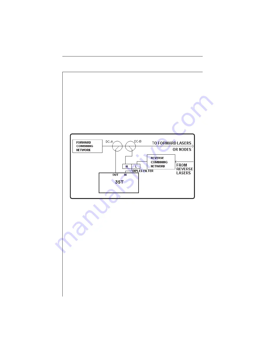
5.3 INSTALLATION OF 3ST SWEEP TRANSMITTER
Properly connecting the 3ST and setting up the proper levels are
perhaps the two most critical steps in installing the Stealth Sweep
System. Improper 3ST connections or incorrect levels on either the
input or the output can result in the 3SR giving erroneous or inconsis-
tent results. A simple and common method of connecting the 3ST in
the system at the headend works for both forward and reverse
sweeping.
In the Sweep mode, the 3ST should never see video or carrier levels
above +12 dBmV on its input. The forward sweep points being
inserted into the system by the 3ST should be 14 to 16 dB below the
video carrier levels at the 3ST input. The forward telemetry signal
generated by the 3ST should be 4 dB higher than the sweep insertion
points, or 10 dB below the video carrier levels. Figure on page 5-14
shows a graphical display of the relationship of the system's video
carriers, the sweep insertion points, and the forward telemetry signal.
When sweeping, this relationship can be observed on the 3ST display
except for telemetry, which can not be seen.


