background image

Document #10-32813 Rev A; June 07, 2019

Page

23

of 69

Configure Ethernet with Dashboard

Before you begin

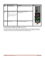
If you do not already have Dashboard on your machine, you will find it on the SD: drive of your RMA PLUS. Connect a
Mini-B USB cable to the RMA PLUS, eject the SD: drive to mount it to your PC, open the Software folder, open Dash-
board folder, and then extract the Dashboard .zip files to a new directory on your PC. You may then launch Dash-
board.exe from there.

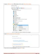
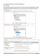
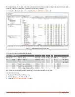
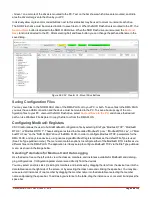
1. Launch Dashboard. The discovered RMA PLUS should be under the “USB Devices” tree node.

Figure 18: Dashboard: USB Devices in Tree Node
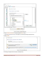
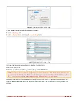
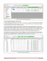
2. Expand the

RMA PLUS

to see basic device information.

Figure 19: RMA PLUS Expanded in Tree Node

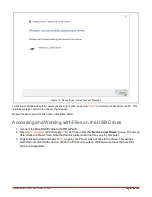
3. Drag and drop the RMA PLUS tree node onto the Device Data pane to upload all parameters.

Figure 20: Dashboard: Drag Device into Data Pane

Содержание RMA PLUS

Страница 1: ...RMA PLUS User Guide 1241 Bundy Boulevard Winona Minnesota USA 55987 Phone 1 507 454 5300 Fax 1 507 452 4507 http www watlow com Document 10 32813 Rev A June 07 2019...

Страница 2: ...nication Slots 11 Earth Ground for USBH and USBD Connectors 11 RMA PLUS Communications Options 12 RMAP AAXX XXXX Standard Options Model 12 RMA PLUS with Communication Options RS 232 RS 485 13 System W...

Страница 3: ...5 Features 36 USB Composite Device 36 Mini B USB Connection for Fast Communication to RM Devices 36 Three Drives in Mass Storage Class 37 Data Logging 37 Ethernet 39 3 Port 10 100 Managed Ethernet Swi...

Страница 4: ...e 53 Chapter 6 Standard Objects Reference 55 Alarm 2 55 Calibration 56 Consumer Data 56 Device 58 LED 58 Real Time Clock 61 Standard Bus and Intermodule Bus 62 Volume 62 Appendix 1 RMA PLUS Setup Keys...

Страница 5: ...r the return call Watlow Customer Service at 1 507 454 5300 for the RMA number l When you call you must provide l Your P O number l Ship to address l Bill to address l Detailed description of the prob...

Страница 6: ...rd party and legacy devices Conceptual Overview l On initialization the RMA PLUS reads the file nor Setup csv from the included USB drive for feature configuration and file paths l Gateway busses and...

Страница 7: ...RTU l Modbus RTU to standard bus or intermodule bus l Modbus RTU to Modbus RTU Software Compatibility Via USB Serial or Ethernet l Watlow Dashboard l Watlow EZ ZONE COMPOSER l LabVIEW by National Inst...

Страница 8: ...Document 10 32813 Rev A June 07 2019 Page 8 of 69 Ordering Part Numbers Figure 1 RMA PLUS Configuration Codes for Ordering...

Страница 9: ...el with a 8 3 4 screw and torque to 10 15 in lb The RMA PLUS can be interconnected with other RM modules via the modular interconnection points on the back panel of all EZ ZONE units See Wiring Power...

Страница 10: ...her RM modules on the DIN rail via the standard EZ ZONE modular interconnection point Slot C Power and Communications Slot C on the bottom rear of the device provides connections for power standard bu...

Страница 11: ...ndard bus EIA 485 T T B EIA 485 connection for EZ ZONE CONFIGURATOR CZ CX CY Intermodule bus Wire for split rail configurations Earth Ground for USBH and USBD Connectors The USB Host and USB D connect...

Страница 12: ...ire Connection Point RMA PLUS Communications Options RMAP AAXX XXXX Standard Options Model RMAP AAXX XXXX stand alone RMA PLUS in slot A D is the basic model with Ethernet USB only You can use either...

Страница 13: ...ls RMA PLUS with Communication Options RS 232 RS 485 RMAP 2XXX XXXX models include current communication options RS 232 RS 485 module in slot B E Note that the 6 and 7 Ethernet ports are separate so y...

Страница 14: ...ignated for two separate DIN rails with interconnected RM modules When designing your hardware layout for a split rail system consider the available power supply and the loading effect of all modules...

Страница 15: ...ro SD NOR FLASH and RAM Disk drives included with your RMA PLUS If you already use a Watlow RM product and have Watlow USB drivers installed you do not need to reinstall the drivers and may proceed to...

Страница 16: ...ve to the PC When the drive is mounted to the PC you ll see the name of the drive recognized and the PC will have exclusive con trol of the drives In the image below all three drives have been ejected...

Страница 17: ...Other devices and then select Update Driver Software Figure 11 Update Driver Software via Windows Device Manager 6 Select Browse my computer for driver software Figure 12 Choose Browse my computer for...

Страница 18: ...ive 8 Ensure Include subfolders is checked and press the Next button l Note that the full path to the driver in this example is E Software S19 Flashloader USB Drivers 9 Select Install Figure 14 Press...

Страница 19: ...on the RMA PLUS Accessing and Working with Files on the USB Drives 1 Connect the Mini B USB cable to the RMA PLUS 2 Open My Computer Windows key E and look under the Devices and Drives group The remo...

Страница 20: ...in corruption l When a drive is mounted to your PC the PC has exclusive access to that drive All firmware features that require the drive are suspended The default drive state is ejected unmounted to...

Страница 21: ...Document 10 32813 Rev A June 07 2019 Page 21 of 69 Figure 17 Eject the Drives to Unmount from PC...

Страница 22: ...is example shows the data for a Modbus TCP configuration file Field bus or application information is in the first column The bus number follows and dictates the remainder of the record Busses 1 and 2...

Страница 23: ...folder open Dash board folder and then extract the Dashboard zip files to a new directory on your PC You may then launch Dash board exe from there 1 Launch Dashboard The discovered RMA PLUS should be...

Страница 24: ...s as necessary Ethernet 70 0x46 Instance 2 Member ID Member Name Data Type Access NV Min Max Default Comments 16 0x10 IP Address Mode ENUM16 RW F 1284 1281 DHCP 1284 FIXED 55 0x37 Statis IP Address St...

Страница 25: ...onnect an Ethernet cable from your PC to either port of the RMA PLUS NOTE The PC s network interface configuration is outside the scope of this document It should be con figured for a static IP addres...

Страница 26: ...r zip file from watlow com onto your PC and then extract the files to a directory on your PC 2 Open the newly created CsvCreator directory and double click CsvCreator exe to open the application 3 Not...

Страница 27: ...that parameter Each time you hover over or move off of a parameter the parameter value is refreshed If the parameter is an enu meration the enumeration text is shown in addition to the numeric value...

Страница 28: ...allows the user to build a Modbus configuration file by selecting File Type Modbus TCP Modbus RTU 6 or Modbus RTU 7 These settings are stored in a file called ModbusTcp csv ModbusRTU6 csv or Mod busR...

Страница 29: ...bers the selected rows starting with the register address of the first selected row l Add Separator Below Current Row allows you to add a separator to the table view for readability If there is duplic...

Страница 30: ...ems are added to the table If the product RMC RME has more than one set of Modbus maps be sure to configure the product with the correct map prior to starting the CSV Creator application This will all...

Страница 31: ...will be green The status bar will also be green and will state the drive letter rep resents the NOR FLASH drive on the PC 4 Select the Load from RMA PLUS button Figure 32 Load from RMA PLUS Button Not...

Страница 32: ...rmation about this feature Applying Configuration Changes to the RMA PLUS For the RMA PLUS to accept and start using the changes to the files after they are written to the RMA PLUS internal drives the...

Страница 33: ...odbus RTU Master If the model number is RMAP 2AXX XXXX then the device will have a card in the adjacent slot that provides two addi tional serial ports for connection to Modbus RTU devices via RS 232...

Страница 34: ...e Event Out 22 0x16 19 0x13 A D 249 Profile Event Out 22 0x16 20 0x14 A D 250 Profile Event Out 22 0x16 21 0x15 A D 1001 Function Key 3 0x03 24 0x18 D 239 Logic 27 0x1B 34 0x22 D 244 Timer 31 0x1F 10...

Страница 35: ...4 0x04 A 142 Analog Input 57 0x39 4 0x04 A 161 Cool Power 75 0x4B 42 0x2A A 160 Heat Power 75 0x4B 41 0x29 A 73 Power 75 0x4B 43 0x2B A 242 Set Point Closed 75 0x4B 44 0x2C A 243 Set Point Open 75 0x...

Страница 36: ...ou install Watlow USB device drivers the RMA PLUS is recognized in your PC Device Manager under Watlow and the drives are listed under Disk Drives Figure 34 RMA PLUS in Windows device manager Mini B U...

Страница 37: ...the SD card inserted If necessary you may upgrade the SD card to a larger capacity and or class if the new card is high capacity SDHC Extended capacity micro SD cards SDXC are not supported by this d...

Страница 38: ...here Z Zone ID C Class ID M Member ID I Instance ID l A R N for Modbus records where A Address R Register N Number of Registers l Headers are only appended once when the file size equals zero l The fo...

Страница 39: ...of the switch internal connection Ports 1 and 2 are for user connections IMPORTANT The embedded switch will reset along with the RMA PLUS breaking connection to downstream device s Therefore carefull...

Страница 40: ...more records to the setup file Setup Key MACA 1 3 Addressing The RMA PLUS currently implements IPV4 static and DHCP addressing Static addressing is the preferred method If DHCP is selected and the de...

Страница 41: ...This ser vice is enabled by default for all model numbers It may be disabled by writing No to the Modbus TCP Enable mem ber NOTE A reset is required for this change to take effect Modbus TCP does not...

Страница 42: ...eption unless the above condition is violated Register Bus Segment Zone Class Instance Member Refresh Count 0 1 0 0 1 1 1 0 Dev 1 Hardware ID 1000 1 0 0 36 1 19 0 RTC 1 Timestamp HTTP Server The RMA P...

Страница 43: ...rive to the PC by right clicking the drive and selecting Eject to view or mdify the HTTPs files l HTTP server files are in the sd Https directory Index html is the default file returned when you navig...

Страница 44: ...name path of the HTTP server configuration file Elements in this file are used to display system parameters on custom web pages To use this feature add this record to the setup file Setup Key HTTPs 5...

Страница 45: ...supports three token key formats and searches them in the following order 1 If the format is CxxIxxMxx then the value is expected to be a member of the RMA PLUS where Cxx is the stand ard bus Class I...

Страница 46: ...r Zone01 html or http 192 168 0 100 Zone01 html and see the new HTML page with live data for Zone 1 Notes l HTML files are stored on the micro SD card by default This path cannot be changed at run tim...

Страница 47: ...NTP Address The RMA PLUS implements a Simple Network Time Protocol SNTP client If the configuration key SntpAddress is present the RMA PLUS will attempt to synchronize its time with the configured SNT...

Страница 48: ...t Gateway Octet 1 UINT8 RW F 0 255 192 29 0x1D IP Fixed Default Gateway Octet 2 UINT8 RW F 0 255 168 29 0x1D IP Fixed Default Gateway Octet 3 UINT8 RW F 0 255 0 29 0x1D IP Fixed Default Gateway Octet...

Страница 49: ...16 bit word register order of multi register data types is low high by default but may be changed to suit the client application See Modbus for member documentation The object model for the Modbus RTU...

Страница 50: ...ng busses when Modbus RTU 7 is configured as a slave Setup Key Modbus RTU7 Key Values Feature Definition RtuFc6 0 FALSE Master uses Function Code 16 exclus ively 1 TRUE Master uses Function Code 6 for...

Страница 51: ...er volume exist on the same device changes cannot be saved to non volatile memory if the NOR FLASH drive is mounted locked Standard Bus and Intermodule Bus Addressing The RMA PLUS uses a proprietary R...

Страница 52: ...1 1 0 PCs software Masters 2 1 3 2 4 3 2 1 4 EZ ZONE RUI RMZ RMA PLUS 2 5 3 6 4 7 5 8 6 9 7 10 8 11 3 1 12 Field Communications Cards 2 13 3 14 4 15 4 1 16 Slaves EZ ZONE ST PM RM 2 17 3 18 4 19 5 20...

Страница 53: ...tes self or the RMA PLUS in this case Using Zone 0 is agnostic of changes to the standard bus logical address If you wish to use the system configuration file to set your Eth ernet parameters change t...

Страница 54: ...54 of 69 Bus Segment Zone Class Instance Member Representation Value 0 0 0 70 2 55 9 192 168 0 100 ETH 2 Static IP Address 0 0 0 70 2 56 9 255 255 255 0 ETH 2 Static IP Subnet Mask 0 0 0 70 2 57 9 19...

Страница 55: ...m 2 10 75 Control Loop 2 4 If RMAP 8AXX XXXX 100 Consumer Data 16 101 Module Limit 1 If RMAP 8AXX XXXX 102 Volume 3 210 Optic Sensing 4 If RMAP 8AXX XXXX 211 Calibration 4 If RMAP 8AXX XXXX New object...

Страница 56: ...lock battery voltage Calibration 211 0xD3 Instance 1 RTC Battery Voltage Member ID Member Name Data Type Access NV Min Max Default Comments Description 84 0x54 Factory Gain FLOAT R F 3 40E 38 3 40E 38...

Страница 57: ...t Out C 236 Profile Event Out D 247 Profile Event Out E 248 Profile Event Out F 249 Profile Event Out G 250 Profile Event Out H 126 Limit 1142 Digital I O 1001 Function Key 239 Logic 230 Compare 231 C...

Страница 58: ...the face of the device By default three of the LEDs indicate the state of a USB Device drive but this is configurable Functions l Off The LED will be OFF l Output Choose a source color red green or y...

Страница 59: ...1 Process Value 238 Linearization 1697 Wattage 1699 Load Voltage 1183 Load Resistance 6 Alarm 233 Profile Event Out A 234 Profile Event Out B 235 Profile Event Out C 236 Profile Event Out D 247 Profil...

Страница 60: ...Flashing Yellow 204 Ignore 18 0x12 Value 4 FLOAT RW F 99999 0 99999 0 0 0 19 0x13 Color 4 ENUM16 RW F 62 62 Off 1718 Red 1719 Green 1720 Yellow 1721 Flashing Red 1722 Flashing Green 1723 Flashing Yel...

Страница 61: ...red up the RTC will automatically adjust the clock for Daylight Saving Time DST following the currently established rules l The battery voltage may be monitored periodically via communications but sho...

Страница 62: ...No 106 Yes 3 0x03 Logical Address UINT8 RW F 1 17 17 4 0x04 Physical Address UINT8 R 0 16 16 5 0x05 RS 485 Master Slave ENUM16 R 1277 1277 Master 1278 Slave 6 0x06 Local Remote ENUM16 R 1329 1328 Loca...

Страница 63: ...nt 10 32813 Rev A June 07 2019 Page 63 of 69 Volume 102 0x66 Instances 1 3 16 0x10 Refresh ENUM16 RW 59 59 No 106 Yes 17 0x11 Start Stop ENUM16 RW 59 59 No 106 Yes 18 0x12 Format ENUM16 RW 59 59 No 10...

Страница 64: ...led the value is set to 0 software tools will not discover the device This record is not in the setup csv file by default To use this feature add this key and value to the setup csv file Setup Key Dis...

Страница 65: ...s gateway file lives This file associates Modbus RTU registers with data points from any of the three remaining busses when Modbus RTU 7 is configured as a slave Setup Key Modbus RTU7 Key Value Featur...

Страница 66: ...5 4 SNTP Cli ent Ethernet IPV4 address of a SNTP server as a string This record is not a member of the default file and therefore the feature is disabled If you wish to use this feature you must add t...

Страница 67: ...Document 10 32813 Rev A June 07 2019 Page 67 of 69 Appendix 2 Declaration of Conformity...

Страница 68: ...Document 10 32813 Rev A June 07 2019 Page 68 of 69...

Страница 69: ...nstall Success Message 19 Figure 16 Windows Devices View All Drives Mounted to the PC 20 Figure 17 Eject the Drives to Unmount from PC 21 Figure 18 Dashboard USB Devices in Tree Node 23 Figure 19 RMA...

Отзывы: