background image

8

Master Programming Mode

When the Master Programming Mode is entered, all 
available option setting displays may be viewed and set 
as needed. Depending on current option settings, some 
parameters cannot be viewed or set.

Setting the Time of Day

1.   Press and hold either the Up or Down buttons until the 

programming icon replaces the service icon and the 
parameter display reads TD.

2.  Adjust the displayed time with the Up and Down buttons.
3.   When the desired time is set, press the Extra Cycle button 

to resume normal operation. The unit will also return 
to normal operation after 5 seconds if no buttons are 
pressed.

Entering Master Programming Mode

Set the Time Of Day display 
to 12:01 P.M. Press the Extra 
Cycle button (to exit Setting 
Time of Day mode). Then 
press and hold the Up and 
Down buttons together until the programming icon replaces 
the service icon and the Display Format screen appears.

Exiting Master Programming Mode

Press the Extra Cycle button to accept the displayed settings 
and cycle to the next parameter. Press the Extra Cycle 
button at the last parameter to save all settings and return 
to normal operation. The control will automatically disregard 
any programming changes and return to normal operation 
if it is left in Master Programming mode for 5 minutes without 
any keypad input.

Resets

:

Soft Reset:

 Press and hold the Extra Cycle and Down buttons 

for 25 seconds while in normal Service mode. This resets all 
parameters to the system default values, except the volume 
remaining in meter immediate or meter delayed systems 
and days since regeneration in the time clock system.

Master Reset: 

Hold the Extra Cycle button while powering up 

the unit. This resets all of the parameters in the unit. Check 
and verify the choices selected in Master Programming 
Mode.

1. Display Format (Display Code DF)

This is the first screen that appears when entering Master 
Programming Mode. The Display Format setting specifies 
the unit of measure that will be used for volume and how 
the control will display the Time of Day. This option setting 
is identified by “DF” in the upper left hand corner of the 
screen. There are three possible settings:

CAUTION: Before entering Master Programming, please contact your local professional water dealer.

Display Format Setting

Unit of Volume

Time Display

GAL

U.S. Gallons

12-Hour AM/PM

Ltr

Liters

24-Hour

225

2. Valve Type (Display Code VT)

Press the Extra Cycle button. Use this display to set the Valve 
Type. The Valve Type setting specifies the type of cycle 
that the valve follows during regeneration. Note that some 
valve types require that the valve be built with specific 
subcomponents. Ensure the valve is configured properly 
before changing the Valve Type setting. This option setting 
is identified by “VT” in the upper left hand corner of the 
screen. There are 2 possible settings:

3. Control Type (Display Code CT)

Press the Extra Cycle button. Use this display to set the 
Control Type. This specifies how the control determines when 
to trigger a regeneration. For details on how the various 
options function, refer to the “Timer Operation” section of 
this service manual. This option setting is identified by “CT” in 
the upper left hand corner of the screen.
There are four possible settings:

Meter Delayed: Fd
Meter Immediate: FI
Time Clock: tc
Day of Week: dAY

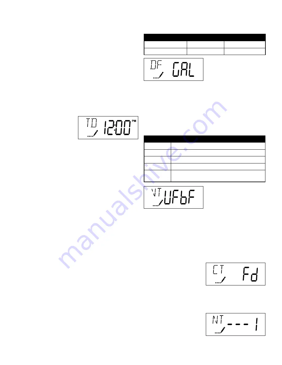
4. Number of Tanks (Display Code NT)

Press the Extra Cycle button. Use this display to set the 
Number of Tanks in your system. This option setting is 
identified by “NT” in the  
upper left hand corner of the  
screen. There are two possible  
settings:

Single Tank System: 1

Abbreviation

Parameter

df1b

Standard Downflow/Upflow Single Backwash

df2b

Standard Downflow/Upflow Double Backwash

Fltr

Filters

UFbF

Upflow Brine First (used for 6200 upflow softener valve)

UFtr

Upflow Filter to be used with 6200 upflow backwashing  

filter valve

Содержание 6200 SXT

Страница 1: ...6200 SXT Upflow Control Valve for Water Conditioning and Treatment Purposes Service Manual...

Страница 2: ...al This unit is designed to be installed on potable water systems only This product must be installed in compliance with all state and municipal plumbing and electrical codes Permits may be required a...

Страница 3: ...let Valve Alone GPM Piston Standard Upflow Continuous 21 Peak 25 psi drop 26 Cv flow at 1 psi drop 5 5 Max backwash 25 psi drop 17 Max Rapid Rinse 25 psi drop 10 Regeneration Downflow Upflow Upflow on...

Страница 4: ...n line flow control 4 Cut the distributor tube 1 88 4 7 cm below the top of the tank 5 Lubricate the distributor O ring seal and tank O ring seal Place the main control valve on tank Note Only use sil...

Страница 5: ...le plumbing codes Please refer to the manual regeneration part of the timer operation section in this manual 1 Position the valve to the brine slow rinse position Ensure the unit is drawing water from...

Страница 6: ...nters the Program Mode with the valve in service While in the Program Mode the control continues to operate normally monitoring water usage and keeping all displays up to date Control programming is s...

Страница 7: ...Override The system s day override setting RT Regen Time The time of day the system will regenerate BW BD RR BF Regen Cycle Step Times The time duration for each regeneration step Ad justable from OFF...

Страница 8: ...ode DF This is the first screen that appears when entering Master Programming Mode The Display Format setting specifies the unit of measure that will be used for volume and how the control will displa...

Страница 9: ...t capacity of the system media Enter the capacity of the media bed in grains of hardness when configuring a softener system and in the desired volume capacity when configuring a filter system This opt...

Страница 10: ...rner of the screen The abbreviations used are listed below If the system has been configured with the OTHER valve type the regeneration cycles will be identified as R1 R2 R3 R4 R5 and R6 Each cycle st...

Страница 11: ...ess The hardness of the inlet water used to calculate system capacity for metered systems RC Reserve Capacity The fixed reserve capacity CD Current Day The current day of week NOTES Some items may not...

Страница 12: ...te since the last regeneration cycle This option setting is identified by PF in the upper left hand corner of the screen 4 Press the Up button Use this display to view the Hours in Service since the l...

Страница 13: ...HE PROPERTY OF PENTAIR WATER TREATMENT REPRODUCTION USE DISCLOSURE OR TRANSMISSION OF THIS DOCUMENT OR DETAILS CONTAINED HEREIN IN PART OR IN WHOLE IS PROHIBITED WITHOUT THE WRITTEN CONSENT OF PENTAIR...

Страница 14: ...r Flow Washer BLFC 16 19335 Fitting BLFC 3 8 20 19625 Nut Assembly 3 8 Plastic 95 60422 XX BLFC Assembly Specify XX GPM 6200 Service Kits Brine Line Flow Control Kits 6200 Service Kits Brine Valve Dwg...

Страница 15: ...r Filter 66 18275 X Throat Injector Specify Size X 65 18274 X Nozzle Injector Specify Size X 12 10141 O Ring 010 67 18273 Generator Vortex 13 13771 O Ring 012 90 61514 XX Injector Assembly Specify Siz...

Страница 16: ...Service Kits Other Parts Dwg Part Part Description 37 17020 Screw Stl Hex 6 20 X 3 8 51 040050 Screw Hex Washer 34 42919 Cam Brine 85 43107 Label Cam Position Softener 43121 Label Cam Position Filter...

Страница 17: ...lack 43052 02 Cover Cream 54 10231 Screw Slot Hex 1 4 20 X 1 2 49 19597 Motor 24V 50 60 Hz 35 43053 01 Backplate Black 43053 02 Backplate Cream 41 19581 Bracket Drive 43 10302 Insulator Limit Switch 3...

Страница 18: ...636 Yoke 1 1 4 NPT 40636 49 Yoke 1 1 4 Sweat Item No Quantity Part No Description 1 1 19645 Body Safety Brine Valve 2310 2 1 19803 Safety Brine Valve Assembly 3 1 19804 Screw Socket Hd Set 10 24 X 75...

Страница 19: ...oft Water To Drain Hard Water Soft Water To Drain Hard Water Soft Water To Drain Hard Water Soft Water To Drain Hard Water Soft Water Hard Water Soft Water Hard Water Soft Water To Drain Hard Water So...

Страница 20: ...Water Conditioner Flow Diagrams 20 Rapid Rinse Position Brine Refill Position Hard Water Soft Water To Drain Hard Water Soft Water To Drain...

Страница 21: ...Wiring Diagram 21...

Страница 22: ...6200SXT Upflow Brining Rates 22 6200SXT Upflow Brining Rates with Water 20 PSI Regulated Cap...

Страница 23: ...valve body and discard it 4 Apply silicone lubricant to the gasket and install around oval extension on injector cap 5 Apply silicone lubricant to two new o rings and install over 2 bosses of the new...

Страница 24: ...ttom of brine valve hole 4 Apply silicone lubricant to new o ring and install at bot tom of brine valve hole 5 Apply silicone lubricant to o ring on new valve assembly and press into brine valve hole...

Страница 25: ...ne cam Close the front cover of the control valve 7 Reconnect meter cable Piston screw Timer Assembly Self tapping screw Screw Screw Screw Screw Bracket Brine Valve Brine Cam Meter Cable 1 Disconnect...

Страница 26: ...1 to 5 of timer replace ment 2 Use a flat head screw drive on the notch of the valve body as shown to loosen the piston cartridge pull the cartridge out of the body using pliers 5 Reinstall the timer...

Страница 27: ...is Replace it with a new washer if neccessary 4 Re install the BLFC housing and re tainer 1 Disconnect the brine line retainer clip 1 Disconnect the drain line retainer clip 2 Remove the DLFC assembly...

Страница 28: ...the circuit board from valve front cover by removing two screws 2 Disconnect the meter cable and power head harness from the circuit board 3 Replace and connect the new cir cuit board on the front co...

Страница 29: ...29 6200 SXT Valve Dimensional Drawings All dimensions are in Inches mm...

Страница 30: ...30 57 40 51 37 24 53 52 54 36 37 37 37 55 32 45 42 43 44 34 46 47 48 41 49 31 33 35 50 60 81 82 85 6200 SXT Control Valve Exploded View...

Страница 31: ...13 11 29 58 6 59 56 76 12 64 13 67 65 66 68 72 73 74 17 75 71 70 86 69 61 63 62 77 78 79 80 84 17 87 88 27 92 94 89 95 93 91 90 Use in case of filter valve 96 23 Replace with in filter valve 91 No O...

Страница 32: ...KET 6200 PLASTIC 53 1 15137 SCREW HEX WASHER HEAD 54 3 10231 SCREW SLOT HEX 1 4 20 X 1 2 Item No Qty Part No Description 55 1 13363 WASHER HAGUE DRIVE 56 1 40058 SCREEN INJECTOR 57 1 43054 03 LABEL NO...

Страница 33: ...e A Air in water system A Assure that well system has proper air eliminator control Check for dry well condition B Improperly sized drain line flow control B Check for proper drain rate 6 Iron in cond...

Страница 34: ...ion and verify that it functions correctly If the error re occurs unplug the unit and contact technical support 2 Regen Failure The system has not regenerated for more than 99 days or 7 days if the Co...

Страница 35: ...35...

Страница 36: ...ll Free Phone 1 877 581 1833 Canada Headquarters WaterGroup Companies Inc 490 Pinebush Road Unit 1 Cambridge ON N1T 0A5 Canada Toll Free Phone 1 877 288 9888 www watergroup com Distribution Locations...

Отзывы: