11.11
2
OL.1010EX.
M.
-
-
-
-
II 3 D
CLASS II DIV.2
MVE
-
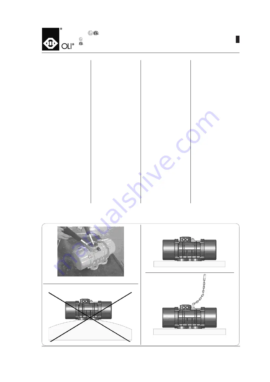
Powierzchnia, na której ma być za
-
instalowany silnik wibracyjny, musi
być równa
(maks. 0,25 mm / maks.
0,01 cala)
, aby nogi silnika miały z
nią dobrą styczność i opierały się
równomiernie. Dzięki temu uniknie
się wewnętrznych naprężeń, które
mogą doprowadzić do pęknięcia
nóg silnika (fig. 2 - 3)
.
-
Do zamocowania silnika należy
użyć śrub (jakość 8.8), nakrętek
(jakość 8.8) oraz podkładek pła
-
skich kat.
A wg UNI6592 – patrz
tabele na stronach T.18÷35
.
-
Do dokrecania śrub należy użyć
klucza dynamometrycznego, na
-
stawionego zgodnie z tabelą na
stronie
T.18÷35
.
-
Należy pamiętać o tym, że przy
-
czyną większości zakłóceń i awarii
jest nieprawidłowe ustalenie ele
-
mentów oraz niewystarczające do
-
ciągniecie połączeń śrubowych
.
-
Silnik wibracyjny należy zabezpie
-
czyć przed upadkiem za pomocą
łańcucha o takiej długości i grubo
-
ści, aby w razie obluzowania silnik
mógł spaść najwyżej 15 cm (6 cali)
– patrz fig. 4.
Przed uruchomieniem oraz po
pierwszych 24 godzinach eksploa
-
tacji należy sprawdzić następujące
elementy
:
-
śruby mocujące silnika wibra
-
cyjnego oraz spawy płyt i żeber
wzmacniających (jeśli są);
- i
linkę wzgl. łańcuch zabezpiecza
-
jący przed upadkiem;
-
kabel zasilający
.
INSTALLATION
EINBAU
INSTALLATION
INSTALACJA
Fig. 1
Fig. 2
Fig. 3
Fig. 4
OK
NO
- La surface de fixation doit être plate
(max 0,25 mm/ max 0,01 in.)de ma
-
nière à ce que les pieds appuient
uniformément et soient parfaitement
en contact avec la surface de fixa
-
tion, pour éviter des tensions internes
pouvant provoquer la rupture des
pieds du motovibrateur (fig. 2 - 3).
- Pour fixer le motovibrateur utiliser
des boulons (qualité 8.8), des écrous
(qualité 8.8) et rondelles plates cat.
A UNI 6592 comme indiqué dans les
tableaux pages T.18÷35.
- Utiliser une clé dynamométrique
réglée d’après les indications de la
table page T.18÷35.
- Ne pas oublier que la plupart des pan
-
nes et des dysfonctionnement sont
dues à un serrage ou une fixation
mal exécutée.
- Ancrer le motovibrateur à la structure
avec une chaîne d’une longueur et
section de 15 cm (6 pouces) ou un
câble métallique permettant de le
soutenir en cas de chute par décro
-
chage accidentel. (fig.4)
Avant la mise en marche et après
les 24 premières heures de travail
contrôler :
- les boulons de fixation du motovibra
-
teur et les soudures des plaques et
des nervures de renfort ;
- le câble ou la chaîne d’ancrage;
- le câblage d’alimentation.
- Die Anschlussfläche muss eben
sein (max. 0,25 mm/ max. 0,01 Zoll),
damit die Füße des Unwuchtmotors
gleichmäßig aufstehen und einen
perfekten Kontakt mit der Befe
-
stigungsfläche haben, um interne
Spannungen zu vermeiden, die zum
Bruch der Füße des Unwuchtmotors
führen könnten (Abb. 2 - 3).
- Zum Befestigen des Unwuchtmo
-
tors sind Schrauben (Festigkeit
8.8), Muttern (Festigkeit 8.8) und
Flachscheiben Kat. A UNI6592 zu
verwenden, wie es in den Tabellen
auf Seite T.18÷35 angegeben wird.
- Einen Drehmomentschlüssel benut
-
zen, der gemäß der Angaben der
Tabelle von Seite T.18÷35 eingestellt
ist.
- Nicht vergessen, dass der größte
Teil der Störungen und Betriebsaus
-
fälle darauf beruhen, dass die Teile
schlecht befestigt und die Verschrau
-
bungen schlecht angezogen worden
sind.
- Den Unwuchtmotor mit einer Kette
von solcher Länge und Querschnitt
befestigen, dass der Unwuchtmotor
maximal 15 cm (6 Zoll) tief fallen
kann, falls es zur Ablösung kommt
(Abb. 4).
Vor der Inbetriebnahme und nach den
ersten 24 Betriebsstunden folgendes
prüfen:
- die Befestigungsschrauben des
Unwuchtmotors und die Schweiß
-
nähte der Verstärkungsplatten und
-rippen
- den Draht bzw. die Kette zur Ver
-
ankerung
- das Speisekabel.
- The fixing surface must be level
(max 0.25 mm/ max 0.01 in.) so that
the vibrator feet rest uniformly and
perfectly in contact with the fixing
surface, to avoid internal stresses
which can lead to breakage of the
vibrator feet (fig.2 - 3).
- To fix the electric vibrator, use bolts
(quality 8.8), nuts (quality 8.8) and
flat washers belonging to cat. A
UNI6592 as shown in the Tables on
Page T.18÷35.
- Use a dynamometric wrench ad
-
justed according to the indications
in the Table on page. T.18÷35.
- Remember that most faults and
breakdowns are due to incorrect
fixing and locking.
- Anchor the electric vibrator using
a chain having a length and cross
section suitable for supporting the
electric vibrator with a maximum
fall of 15 cm (6 inches), in case of
accidental detachment. (fig.4)
Before start up and after the first 24
hours of operation check:
- the electric vibrator fixing bolts and
the welding of the reinforcing plates
and ribbing;
- the anchoring cable or chain;
- the power cable;
04


