


PT 6 /...
Maintenance
wc_tx000567gb.fm
47
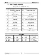
5.25 Wiring Diagram Components
(0007174 > Rev 119; 0007175 > Rev 122)
Ref.
Component
Ref.
Component
1
Cylinder head temperature
switch
14
Oil temperature sensor
2
Engine harness
15
Engine Control Unit (ECU)
3
Extension harness
16
Battery
4
Glow plug
17
Starter solenoid
5
Throttle solenoid
18
Voltage regulator
6
Hour meter
19
Low oil pressure switch - N.O.
7
Control panel
20
Low oil pressure switch - N.C.
8
Keyswitch
21
Diagnostic port
9
Glow plug relay
22
Cam RPM sensor
10
15A Fuse
23
Control solenoids
11
20A Circuit breaker
24
Engine alternator
12
Pump sensor
25
80A Fuse
13
Engine RPM sensor
26
Control panel harness
Wire Colors
B
Black
R
Red
Y
Yellow
Or
Orange
G
Green
T
Tan
Br
Brown
Pr
Purple
L
Blue
V
Violet
Cl
Clear
Sh
Shield
P
Pink
W
White
Gr
Gray
LL
Light blue
Содержание PT 6LT
Страница 1: ...Pump PT 6 OPERATOR S MANUAL 0154629en 006 0107 0 1 5 4 6 2 9 E N ...
Страница 2: ......
Страница 11: ...PT 6 Safety Information wc_si000098gb fm 9 2 7 Label Locations wc_gr001145 1 3 7 6 3 8 10 9 5 6 4 12 11 2 ...
Страница 17: ...PT 6 Technical Data wc_td000099gb fm 15 3 5 Dimensions wc_gr001154 ...
Страница 27: ...PT 6 Operation wc_tx000261gb fm 25 wc_gr003210 3 1 2 e g 3 1 2 d a b c f ...
Страница 41: ...PT 6 Maintenance wc_tx000567gb fm 39 wc_gr003206 a b g c d d e e f g g e f g 0 15 0 75 mm 0 005 0 025 in ...
Страница 53: ......
Страница 54: ......
Страница 55: ......
Страница 56: ......
Страница 57: ......
Страница 58: ......
Страница 59: ......
Страница 60: ......
Страница 61: ......
Страница 62: ......
Страница 63: ......
Страница 64: ......
Страница 65: ......