67
16. 2-axis coordinate tables K400 and K600
16.6 Mounting kit for mountable vernier scales for 2 axes and spindle Y-axis
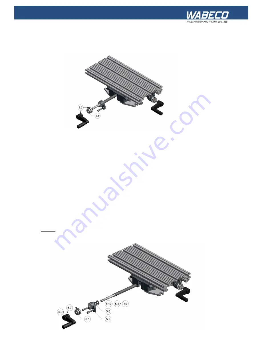
16.6.1 Replacement of the spindle Y-axis
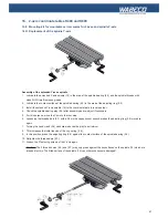
Assembly of the extended Y-axes spindle
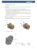
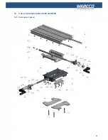
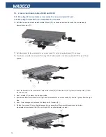
1. Lubricate the extended Y-axis spindle (15) in the area of the spindle bearing (5.2) and the spindle threads with
class 2NLGI multi-purpose grease
2. Lubricate the contact surface of the spindle bearing (5.2) in the area of the adjusting ring (5.5)
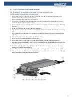
3. Install the extended Y-axis spindle (15) in the coordinate table in reverse order
4. Check the spindle bearing play (5.5) after assembly and re-adjust if necessary
5. For this purpose, move the Y-axis to the rear stop
6. Loosening the threaded pin (5.7) with a 2.5 mm hexagon socket wrench makes the adjusting ring (5.5) movable
again
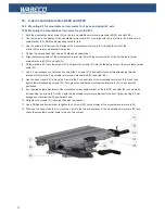
7. Turning the hand crank (5.4) clockwise reduces the play to a minimum.
8. This increases the initial tension of the cup spring (5.6).
9. In this position, press the adjusting ring (5.5) against the contact surface of the spindle bearing (5.2).
10. Retighten the threaded pin (5.7).
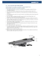
11. Loosen the 2 fastening screws of the Y axis again
Caution:
The 2 threaded pins (5.9) and (5.7) may only press against the key surfaces on the spindle (15) which are
intended for this. The fitted surface of the spindle (15) can otherwise become damaged!
Содержание BF1243
Страница 26: ...26 16 2 Achsen Koordinatentische K400 und K600 16 5 Zeichnung und Legende...
Страница 63: ...63 16 2 axis coordinate tables K400 and K600 16 5 Drawing and legend...
Страница 76: ......

