47
4. Drilling milling stands BF1240 | BF1242 | BF1243 | BF1244
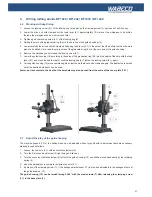
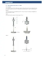
4.6 Working with depth stop
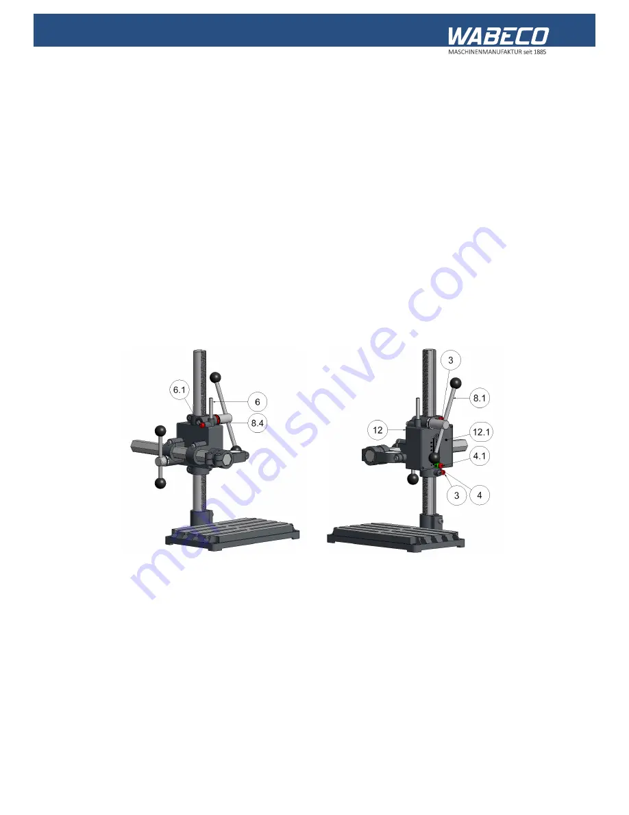
1. Loosen the locking screw (4.1) of the locking ring (4) as well as the clamping screw (3) by means of an Allen key.
2. Lower the drive unit with clamped drill by feed lever (8.1) approximately 10 mm over the workpiece to be drilled,
thereby, the workpiece can be well removed later.
3. Tighten again the locking screw (4.1) of the locking ring (4)
4. Setting the mark of the graduated ring (8.4) to the zero line of the guide housing (12).
5. Lower carefully the drive unit with clamped drill using feed lever (8.1) to the extent that the drill tip touches the work
piece to be drilled. Here, read the scale value of the graduated ring (8.4) at the zero line of the guide housing!
6. Remove the workpeace and release the locking screw (6.1).
7. Lower the guide housing (12) according to the value of the graduation ring (8.4) plus the depth of the hole with the feed
lever (8.1) and move the depth stop (6) until the locking ring (4). Tighten the locking screw (6.1) again.
8. Let the guide housing (12) move upwards again so that the work piece can be clamped again. The depth stop is hereby
set at the desired hole depth can be used.
Faster, but less accurate, the depth of the borehole may also be read from the scale of the cover plate (12.1).
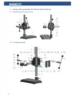
4.7 Adjust the play of the guide housing
The machine support (12) of the drilling stand can be adjusted without play. Should re-adjustment become necessary,
please proceed as follows:
1. Loosen the two nuts (2.1) of the eccentric setscrews (2)
2.
Turn the first eccentric setscrew (2) right using an Allen key
3. Turn the second eccentric setscrew (2) left until the guide housing (12) can still be moved back easily by the retaining
spring (5)
4. when the adjustment is complete re-tighten the nuts (2.1)
5. By means of the clamping screw (11.1) the hexagonal steel boom (11) is play-free adjustable in the hexagonal bore of
the guide housing (12).
The guide housing (12) can be turned through 360 ° with the steel column (7) after releasing the clamping screw
(1.1) in the base plate (1).
Содержание BF1243
Страница 26: ...26 16 2 Achsen Koordinatentische K400 und K600 16 5 Zeichnung und Legende...
Страница 63: ...63 16 2 axis coordinate tables K400 and K600 16 5 Drawing and legend...
Страница 76: ......

