Connect the attachment.
Check the gap again, if there still is a gap repeat the same
procedure.
A
A
t
t
tac
c
hm
m
e
e
n
n
t
t
qu
u
i
i
ck cou
u
p
p
l
l
er
r
Un
n
i
i
v
v
er
r
s
s
al
l
at
t
t
t
a
a
c
c
hm
m
e
e
n
n
t
t
qu
u
i
i
c
c
k cou
u
p
p
l
l
e
e
r
r
(o
o
p
p
t
t
i
i
o
o
n
n
a
a
l
l
eq
q
u
u
i
i
p
p
m
m
e
e
n
n
t
t
)
)
The universal attachment quick coupler is equipped with a
double-acting hydraulic cylinder.
The hook for gripping the attachment is fitted to its piston rod.
Working pressure acts on the piston on the lock cylinder, locking
the attachment in place against the rear bucket pin. This means
that the hook adjusts itself and provides gap-free locking.
Another feature of the universal attachment quick coupler is the
front pin lock (FPL).
Front pin lock (FPL) is a locking mechanism at the front of the
universal attachment quick coupler which hinders the tool to drop
in case of incorrect locking of the rear pin.
Li
i
f
f
t
t
i
i
n
n
g
g
ey
y
e
With the aid of the lifting eye, the machine can be used for lifting
operations. As the lifting eye is positioned on the attachment quick
coupler, it can be used without a bucket. This improves visibility
for the operator and increases the maximum permissible load.
Co
o
n
n
n
n
e
e
c
c
ti
i
n
n
g
g
at
t
t
t
a
a
c
c
hm
m
e
e
n
n
t
t
— un
n
i
i
v
v
er
r
s
s
al
l
at
t
t
t
a
a
c
c
hm
m
e
e
n
n
t
t
qu
u
i
i
c
c
k
cou
u
p
p
l
l
e
e
r
r
WA
A
R
R
N
N
I
I
N
N
G
G
Risk of crushing!
Attachments that move unexpectedly can cause injuries.
Mak
k
e sur
r
e pe
e
op
p
l
l
e
e
sta
a
y out of
f
th
h
e
e
wor
r
kin
n
g area
a
when con
n
n
n
ecti
i
ng
or
r
discon
n
n
n
ec
c
ti
i
ng att
t
a
a
c
c
hm
m
ents
s
.
1 Position the machine on firm level ground.
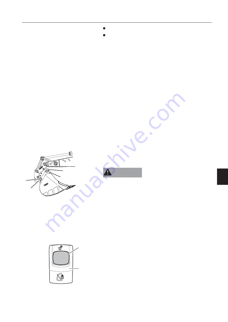
2 Place the attachment quick coupler above the bucket. Make
sure the locking hook (B) is fully retracted before connecting.
To fully retract the locking hook curl in the bucket completely
towards the machine.
3 Initiate the opening of the empty attachment quick coupler as
follows:
Push the red button (1) of the attachment quick coupler switch
(2) on the right instrument panel and push down the upper end
of this switch simultaneously. The switch will be locked in this
position.
A yellow quick coupler symbol and a check message for
unlocked quick coupler will appear in the IC (Instrument
Cluster). Additionally the buzzer sounds continuously.
C
A
A
B
V1152056
A. Bucket pins
B. Locking hook
C. Front pin lock (FPL)
V1148410
1
2
2. Attachment quick coupler switch (right
instrument panel)
Op
p
e
e
r
r
a
a
t
t
i
i
n
n
g
g
te
e
c
c
hn
n
i
i
q
q
u
u
e
e
s
s
Att
t
a
a
c
c
hm
m
e
e
n
n
t
t
s
s
, con
n
n
n
e
e
c
c
ti
i
n
n
g
g
an
n
d
d
di
i
s
s
con
n
n
n
e
e
c
c
ti
i
n
n
g
g
21
1
7
7
Содержание 322001
Страница 7: ...5 5 ...
Страница 146: ...Right mirrors 1 14 44 4 Op pe er ra at ti in ng g in ns str ru uc cti io on ns s ...
Страница 172: ...1 170 Operating instructions Exhaust aftertreatment system ...
Страница 357: ...S Specifications Dimensions 355 ...
Страница 380: ...E EW160E 5 m Monoblock boom 3200 kg Counterweight Blade rear only V1110444 378 Specifications Lifting capacities ...
Страница 381: ...E EW160E 5 m Monoblock boom 3600 kg Counterweight Blade rear only V1110445 Specifications Lifting capacities 379 ...
Страница 386: ...E EW160E 5 1 m Two piece boom 3200 kg Counterweight Blade rear only V1110450 384 Specifications Lifting capacities ...
Страница 387: ...E EW160E 5 1 m Two piece boom 3600 kg Counterweight Blade rear only V1110451 Specifications Lifting capacities 385 ...
Страница 410: ......
Страница 413: ......
Страница 414: ...4 412 Alphabetical index Ref No 20052711 C Volvo Eskilstuna English ...


