T
T
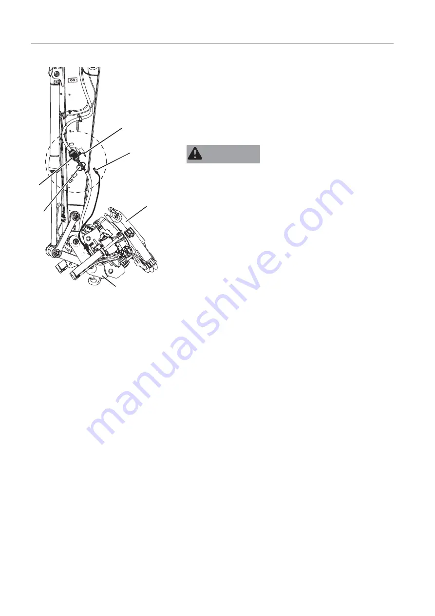
iltrotator control system, description
Operating
The machine’s quick coupler lock (1) can not be opened when the
electrical connector on the tiltrotator is connected to the machine.
This is a safety feature to ensure opening is not done by mistake
when operating the tiltrotator.
Instead the quick coupler switch is used for attaching the
attachment to the tiltrotator’s quick coupler (2).
WA
A
R
R
N
N
I
I
N
N
G
G
Risk of crushing.
Hydraulic or mechanical failure could cause the attachments to
fall, resulting in severe personal injury or death.
Alw
w
ay
y
s pl
l
a
a
c
c
e th
h
e at
t
t
t
a
a
c
c
hment
t
on th
h
e gr
r
ou
u
n
n
d
d
when ins
s
ta
a
l
l
l
l
i
i
n
n
g or
rem
m
ov
v
in
n
g
g
it
t
and
d
mak
k
e sure no
o
bo
o
d
d
y
y
en
n
te
e
rs th
h
e
e
wo
o
r
r
kin
n
g
g
ar
r
ea
a
.
.
In
n
s
s
ta
a
l
l
l
l
i
i
n
n
g
g
th
h
e
e
ti
i
l
l
t
t
r
r
o
o
t
t
a
a
t
t
o
o
r
r
1 Attach the tiltrotator to the machine’s quick coupler (1)
according to information about quick couplers in the quick
coupler section on page
210.
N
N
O
O
T
T
E
E
!
Be careful so no hydraulic or electrical lines are damaged on the
tiltrotator.
2 Place the tiltrotator on the ground and position the machine for
best access to the hydraulic connectors.
3 S
S
top the engine and depressurize the hydraulic system, see
page
221.
.
4 Connect the hydraulic lines on the tiltrotator to the connectors
(C) on the machine. Start with the one on the right hand side
(tank side).
5 Open the stop valves for X1 (D) with a wrench slowly. There
is one stop valve on each side.
6 Open the protection plug (A) for the electrical connector on the
dipper arm and place it next to the electrical connector.
7 Connect the electrical connector (B) on the tiltrotator to the
dipper arm.
8 Install the attachment according to information about the quick
coupler in the quick coupler section on page
210.
V1186228
1
2
D
A
B
C
1
Machine´s quick coupler
2
Tiltrotator´s quick coupler
A Protection plug
B Electrical connector tiltrotator
C Hydraulic connectors
D Stop valve for X1
20
0
8
8
Op
p
e
e
r
r
a
a
t
t
i
i
n
n
g
g
te
e
c
c
hn
n
i
i
q
q
u
u
e
e
s
s
At
t
t
t
a
a
c
c
hm
m
e
e
n
n
t
t
s
s
Содержание 322001
Страница 7: ...5 5 ...
Страница 146: ...Right mirrors 1 14 44 4 Op pe er ra at ti in ng g in ns str ru uc cti io on ns s ...
Страница 172: ...1 170 Operating instructions Exhaust aftertreatment system ...
Страница 357: ...S Specifications Dimensions 355 ...
Страница 380: ...E EW160E 5 m Monoblock boom 3200 kg Counterweight Blade rear only V1110444 378 Specifications Lifting capacities ...
Страница 381: ...E EW160E 5 m Monoblock boom 3600 kg Counterweight Blade rear only V1110445 Specifications Lifting capacities 379 ...
Страница 386: ...E EW160E 5 1 m Two piece boom 3200 kg Counterweight Blade rear only V1110450 384 Specifications Lifting capacities ...
Страница 387: ...E EW160E 5 1 m Two piece boom 3600 kg Counterweight Blade rear only V1110451 Specifications Lifting capacities 385 ...
Страница 410: ......
Страница 413: ......
Страница 414: ...4 412 Alphabetical index Ref No 20052711 C Volvo Eskilstuna English ...


